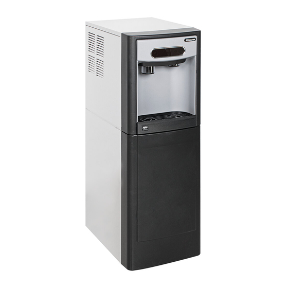
Follett Chewblet 7 Series Manuel d'installation - Page 11
Parcourez en ligne ou téléchargez le pdf Manuel d'installation pour {nom_de_la_catégorie} Follett Chewblet 7 Series. Follett Chewblet 7 Series 20 pages. Ice and water dispenser

6. Complete Potable Water Connection before proceeding.
7.
Secure unit to wall or cove molding with supplied bracket (Fig. 7) to
prevent tipping.
Note: Fasteners must be supplied by installer.
WARNING!
Freestanding unit must be secured to wall to prevent tipping.
Failure to do could result in personal injury or damage to the
unit.
Undercounter Installation
1. Measure to verify that the dispenser will fit in the desired location. A
clearance of at least 3" (7.6 cm) is required behind the dispenser for
the electrical and optional drain connection.
2. Ensure that the finished floor inside the cabinet is flush (level) with
the floor outside the cabinet (Fig. 1). If the cabinet floor is lower
than the finished floor, the cabinet floor must be built up (using
appropriate materials) until it is flush with the finished floor. A flush
floor is required for proper operation and maintenance/service of the
dispenser.
3. Rough-in the electrical service, water line, and optional Drip Tray
Drain Kit*.
Note: The dispenser must be installed such that it can be moved
forward at least 4" (10.16 cm) to allow access to the Bin Lid
Cleaning Spout (Fig. 9.6) for dispenser cleaning and sanitizing.
Take this requirement into consideration during rough-in.
§ Water: supply line (with shut-off valve) connects to the dispenser's
1/4" MPT inlet or John Guest push-in fitting.
*
The optional Drip Tray Drain Kit (item# 00956375) requires a floor drain
within 15 ft (4.5 m) of the dispenser. For detailed installation instructions,
please refer to the instructions shipped with the Drip Tray Drain Kit.
Fig. 6
Fig. 7
floor
Dispenser and Ice Machine - 115 V, 230 V, 220 V
cabinet space
11
