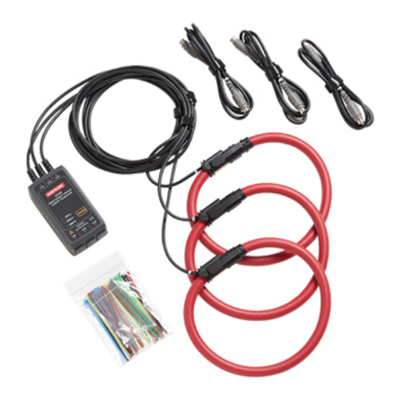
Amprobe CT-53 Manuel d'instruction - Page 7
Parcourez en ligne ou téléchargez le pdf Manuel d'instruction pour {nom_de_la_catégorie} Amprobe CT-53. Amprobe CT-53 14 pages. 3000 a flexible 3-sensor current transducer

Pins of output terminal
Match the
and
mark on the Output Cable
and connect the Cable.
Output signal
Output Terminal
④
• Output signal is between pin 3 and 5 of output terminal and between 4
and 6 of output connector.
• The current clamp is powered via pin 1 and 3 (2.7 to 5.5 V, 200 mA) of
output terminal and pin 2 and 4 of output connector.
• Resistance between 3 and 6 of Output terminal and between 4 and 5 of
Output connector is as stated below:
300A range: 910 kΩ
1000A range: 360 kΩ
3000A range: 510 kΩ
(Resistance cannot be measured while the instrument is powered off.)
• Connecting terminal on DM-5 is symmetrical to above pin
configurations.
mark under CH No.
Power supply
①
②
2.7~5.5V
③
⑥
⑤
Output(+)
Output Connector
①
③
⑤
COM(Output(-))
3
②
2.7~5.5V
④
COM(Output(-))
⑥
Output(+)
