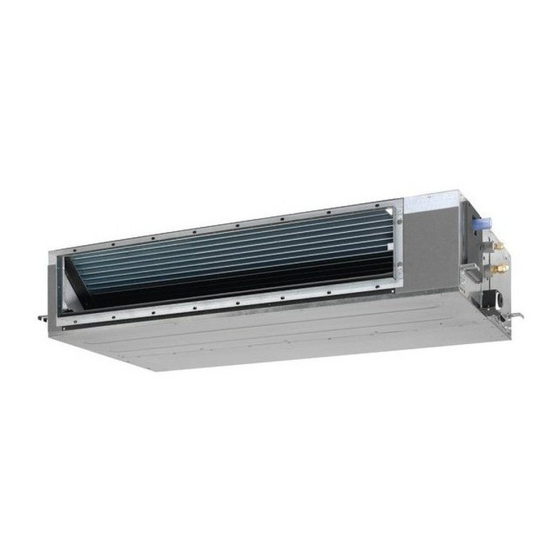
Daikin ADEQ60C2VEB Manuel d'installation - Page 10
Parcourez en ligne ou téléchargez le pdf Manuel d'installation pour {nom_de_la_catégorie} Daikin ADEQ60C2VEB. Daikin ADEQ60C2VEB 16 pages. Siesta
split system air conditioners
Également pour Daikin ADEQ60C2VEB : Manuel d'utilisation (8 pages)

6.
Use only specified wires and tightly connect wires to the terminals.
Be careful that wires do not place external stress on the terminals.
Keep wiring in neat order so that they do not obstruct other
equipment such as popping open the switch box cover. Make sure
the cover closes tight. Incomplete connections could result in
overheating, and in the worse case, electric shock or fire.
Keep total current of crossover wiring between indoor units less than
12 A. Branch the line outside the terminal block of the unit in
accordance with the electrical equipment standards, when using two
power wiring of a gauge greater than 2 mm
The branch must be sheathed in order to provide an equal or greater
degree of insulation as power supply wiring itself.
Wiring example
Fit the power supply wiring of each system with a switch and
fuse as shown in
figure 11
1
Power supply
2
Main switch
3
Fuse
4
Outdoor unit
5
Indoor unit
6
Remote controller (optional accessory)
Complete system example (3 systems)
When using 1 remote controller for 1 indoor unit. (Normal
operation) (See
figure 11
and
Use with 2 remote controllers
For group control
(See figure 14)
It is not necessary to designate an indoor unit address
NOTE
when using group control. The address is automatically
set when the power is activated.
To comply with EN/IEC 61000-3-12
NOTE
must be considered:
(a) Shown in figure is with common power supply
(b) European/International Technical Standard setting the limits for harmonic
currents produced by equipment connected to low-voltage systems with
input current >16 A and ≤75 A per phase.
Precautions
1.
A single switch can be used to supply power to units on the
same system. However, branch switches and branch circuit
breakers must be selected carefully.
2.
For a group control remote controller, choose the remote
controller that suits the indoor unit which has the most functions.
3.
All transmission wiring except for the remote controller wiring is
polarized and must match the terminal symbol.
4.
In case of group control, perform the remote controller wiring to
the master unit when connecting to the simultaneous operation
system (wiring to the slave unit is unnecessary).
7
2
(Ø1.6).
and
figure
12.
figure
12)
(a)
(See figure 13)
(a)
(b)
, following wiring
1 2 3
L N
5.
When controlling the simultaneous operation system with
2 remote controllers, connect it to the master unit (wiring to the
slave unit is unnecessary).
6.
Be sure to connect the wiring to the master unit when combining
with a simultaneous operating multi-type in group control.
7.
Do not ground the equipment on gas pipes, water pipes,
lightning rods or crossground with telephones. Improper
grounding could result in electric shock.
Field setting
Field setting must be made from the remote controller in accordance
with the installation condition.
Setting can be made by changing the "Mode number", "FIRST
CODE No." and "SECOND CODE No.".
For setting and operation, refer to "Field setting" in the
installation manual of the remote controller.
Setting for optional accessories
In case of connecting optional accessories, refer to the operation
manuals provided with the optional accessories and establish
necessary settings.
External static pressure setting
Settings for external static pressure can be achieved in 2 ways:
Using the airflow automatic adjustment function
Airflow automatic adjustment is the volume of blow-off air that
has been automatically adjusted to the rated quantity.
1
Make sure the test run is done with a dry coil.
If the coil is not dry, run the unit for 2 hours with fan only to dry
the coil.
2
Check if the power supply wiring to the air conditioning unit is
completed along with the duct installation.
If a closing damper is installed in the air conditioning unit, make
sure that it is open.
Also check if the air filter is properly attached into the air
passage on the air suction side of the air conditioning unit.
3
If there is more than one air inlet and outlet, adjust the dampers
so that the airflow rate of each air inlet and outlet is conform with
the designed airflow rate.
Make sure the air conditioning unit is in fan operation mode.
Press and set the airflow adjustment button on the remote
controller to change the airflow rate to H or L.
4
Setting the airflow automatic adjustment settings.
When the air conditioning unit is running in fan operation mode
perform the next steps:
-
stop the air conditioning unit,
-
go to field setting mode,
-
select mode No. 21 (or 11 in case of group setting),
-
set the first code No. to "7",
-
set the second code No. to "03".
Return to normal operating mode after setting these settings and
press the ON/OFF operation button. The operation lamp will
light up and the air conditioning unit will start the fan operation
for airflow automatic adjustment.
Do not adjust the dampers during fan operation for
airflow automatic adjustment.
After 1 to 8 minutes, the air conditioning unit stops operating
automatically when the fan operation for airflow automatic
adjustment has been carried out, the operation lamp will be off.
Mode
First
Second
No.
code No.
code No.
01
11 (21)
7
02
03
Setting content
Airflow adjustment is OFF
Completion of airflow adjustment
Start of airflow adjustment
