AMS AS3930 Manuel - Page 9
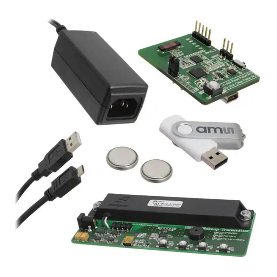
Parcourez en ligne ou téléchargez le pdf Manuel pour {nom_de_la_catégorie} AMS AS3930. AMS AS3930 19 pages. Standard board, demo kit

AS3930 Standard Board
4.2.1.3
Calibrate RC Oscillator
The RC oscillator can be calibrated via the microcontroller or the LC antenna.
4.2.1.4
Antenna Damper
The antenna can be damped in order to limit the range. Therefore, a resistor inside the AS3930 is
switched parallel to the antenna. The value of the resistor can be chosen between 1kΩ to 27kΩ.
4.2.1.5
Gain Reduction
The Gain Reduction of the channel amplifier can be selected between 0dB up to -24dB.
4.2.1.6
Automatic Time-Out
The Automatic Time-Out resets the WAKE pin automatically after a designated time which can be
set between 0ms and 350ms.
4.2.1.7
Envelope Detector Time Constant
The performance of the demodulator can be optimized according to the bit rate and preamble
length. If the bit rate increases the time constant has to decrease. Adjust this ED time constant
according to your symbol rate. The recommended time constants for different symbol rates are
listed in the datasheet.
4.2.1.8
Data Slicer
The threshold of the data slicer can be set to a fixed level by setting the 'hard threshold enable' bit.
This hard threshold can be reduced by setting the 'hard threshold reduction' bit. Otherwise, the
threshold will be dynamically set according to the incoming data signal.
In case the dynamic threshold is used (i.e. the 'hard threshold enable' bit is not set), the data slicer's
noise immunity can be adjusted via the data slicer's time constant. The bigger this time constant is,
the better its noise immunity will be. However, increasing the time constant is only effective if also
the preamble length is increased. Otherwise, the threshold will not have enough time to settle to the
correct value. Therefore, the data slicer's time constant is linked to the minimum preamble length.
The recommended minimum preamble lengths for different data slicer time constants are listed in
the datasheet.
4.2.1.9
Comparator Hysteresis
The comparator hysteresis of the data slicer can be set to either 20mV or 40mV. Furthermore, the
data slicer hysteresis can be selected for only positive edges or both positive and negative edges.
4.2.1.10
Frequency Detection Tolerance
The Frequency Detection Tolerance can be tighter or more relaxed. For details please see the
datasheet.
4.2.1.11
Wakeup Pattern (Manchester)
Select a wakeup pattern here. Each field defines 4 bit. If the transmitted pattern matches the
selected pattern, a wakeup interrupt is generated at the WAKE pin. The WAKE pin goes high.
ams Demo Kit Manual, Confidential
[v1-02] 2014-Jul-10
Page 9
Document Feedback
