COMEM DTI Manuel d'instruction - Page 12
Parcourez en ligne ou téléchargez le pdf Manuel d'instruction pour {nom_de_la_catégorie} COMEM DTI. COMEM DTI 20 pages. Temperature monitoring unit
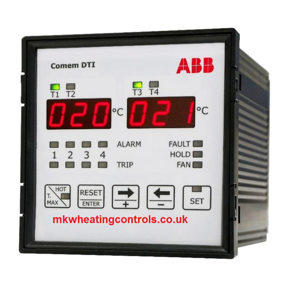
Programming of the device
Selection of the linked channel with the analogue output
This setting is significant only for eDTI model.
This setting is indicated on displays with:
• AN on T1-T2 display
• the linked measure channel on T3-T4 display: CH 1/2/3/4 for the 1/2/3/4
measure channel, ALL to link the measure channel with the higher temperature.
With ← and → keys to select the options.
Confirm with ENTER.
Link channel setting
Channel with higher temperature
Measure channel CH 1
Measure channel CH 2
Measure channel CH 3
Measure channel CH 4
Configuration output signal
This setting is significant only for eDTI model.
In this phase it's possible to define the type of signal of analogue output as 0-20
mA or 4-20 mA.
This setting is indicated on displays with:
AN0 -20 to set the output as 0-20mA or (0 mA = -30°C; 20 mA = 200°C)
AN4 -20 to set the output as 4-20 mA or (4 mA = -30°C; 20 mA = 200°C)
With ← and → keys select the options.
Confirm with ENTER.
4-20 signal setting
Output proportional 0 - 20 mA
Output proportional 4 - 20 mA
Measure channel CH 2
Measure channel CH 3
Measure channel CH 4
12
NOTE
NOTE
TEMPERATURE MONITORING UNIT DTI AND EDTI
T1-T2 display
AN
AN
AN
AN
AN
The maximum load for analogue output
is 400 Ω.
T1-T2 display
AN 0
AN 4
AN
AN
AN
T3-T4 display
ALL
Ch 1
Ch 2
Ch 3
Ch 4
NOTE
T3-T4 display
-20
-20
Ch 2
Ch 3
Ch 4