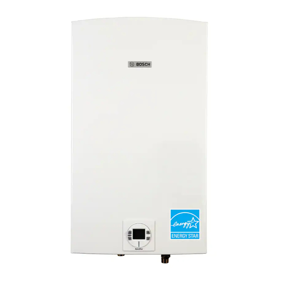
Bosch Evolution 500 Bulletin de service technique
Parcourez en ligne ou téléchargez le pdf Bulletin de service technique pour {nom_de_la_catégorie} Bosch Evolution 500. Bosch Evolution 500 2 pages. Removing and replacing water valve
Également pour Bosch Evolution 500 : Manuel d'utilisation (40 pages), Manuel d'installation (6 pages), Bulletin de service (2 pages), Bulletin de service technique (2 pages), Bulletin de service (2 pages)

Technical Service Bulletin:
A2 Error Code Troubleshooting
Models: C1210ESC, C1210ES, C1050ES, C950ES, 940ES, 940ESO, 830ES, 2400ES,
2700ES, 715ES, C800ES, C920ES/ESC, Integra 500, Evolution 500
Introduction
This procedure must be performed by a qualifi ed technician.
Follow the procedures below and report results to Bosch Technical
Support. This will assist in determining the cause and solution to the
problem.
A2 error code
This error code detected by the fl ue gas limiter
exhaust leak from the combustion chamber.
Flue Gas Limiter
The fl ue gas limiter is a safety device located in the upper right
corner of the heater that is designed to trip (creating an open
circuit) if the chamber outside the heat exchanger exceeds 220 °F or
104 °C.
The limiter will reset itself (closing the circuit) when it cools off, but
the error will still have to be reset manually using the reset button
on the control board.
Tools needed:
Phillips head screwdriver
Digital Multi-meter
Procedure
1.
Press the "reset" button on the control panel of the
heater to clear the error code. If the error code does not
reset or continues to reoccur, proceed with the following
troubleshooting steps.
2.
Confi rm that the heater is installed according to the
specifi cations in the manual.
Confirm that the exhaust and intake pipes are the correct
diameter, material and approved length as explained in the
installation manual provided with your model.
3.
Remove cover per the installation manual and verify that the
plug connector between the fl ue gas limiter (white wires) and
the control unit (black wires) is fi rmly connected (see Fig. 1).
indicates a possible
The fl ue gas limiter (see Fig. 2 A) should not be confused
with the overheat sensor (ECO) on the upper right corner
of the heat exchanger (see Fig. 2 B). The ECO serves an
entirely different function and prompts a different – E9 –
error code.
Figure 1
Figure 2
A
B
