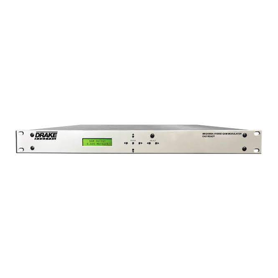
DRAKE MEQ1000A Manuel d'instruction - Page 8
Parcourez en ligne ou téléchargez le pdf Manuel d'instruction pour {nom_de_la_catégorie} DRAKE MEQ1000A. DRAKE MEQ1000A 20 pages. Multiplexing hybrid qam

8 Rear Panel Connections
R1
R2
R3
R4
R5
R6
R7
R8
R9
MEQ1000A - This illustration shows the rear of the MEQ1000A.
The ASI connectors are type BNC female.
The ASI input is used to input SCTE-18 data in ASI format for
use with DTAs and in EAS daisy-chaining applications.
R1; RF OUTPUT – This is the high level (61 dBmV), 54 to 1002 MHz, output from the
MEQ1000A upconverter section.
R2; Contact Closure Terminal - Connect these to EAS Receiver Contact Closure
cables to allow the triggering of EAS activation.
R3; ASI Input -
This is for receiving EAS and DTA data from a Drake EH24, EH24A,
EH244, EH244-IP or MEQ1000A.
R4; Input Module Slot A.
R5; Input Module Slot B.
R6; ASI Output - This output delivers the same multi-program transport stream in ASI as
is sent to the QAM modulator. When the DTA/EAS mode is Enabled, this ASI output no
longer outputs the same data as the QAM output; it now acts as an ASI Loop, outputting
DTA/EAS data only.
R7; RS232 in - Connection to a PC or modem for use with remote control / monitoring
program or for firmware update download.
R8; RS232 OUT - Loop/Daisychain to another MEQ1000A.
R9; AC Line Cord – For connection to the nominal 120 VAC power source. This unit is
designed for use in countries with 120 VAC power standards but the power supply will
accept an input voltage range of 90 VAC minimum to 260 VAC maximum with a power
line frequency of either 50 or 60 Hz.
