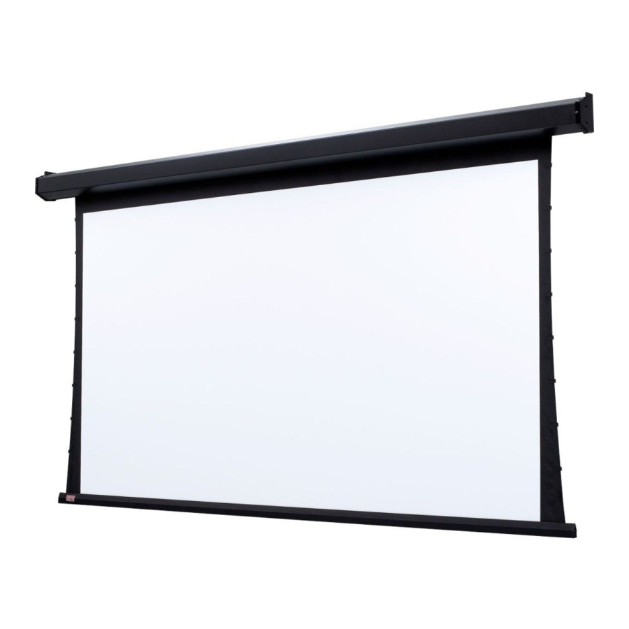
Draper C Series Mode d'emploi
Parcourez en ligne ou téléchargez le pdf Mode d'emploi pour {nom_de_la_catégorie} Draper C Series. Draper C Series 2 pages.

Premier/Series C Crank-Operated Projection Screen by Draper
➀ Read instructions through completely before proceeding; keep them
for future reference. Follow instructions carefully. Installation contrary
to instructions invalidates warranty. Care in both mounting and
correct operation will mean long and satisfactory service from your
Draper screen.
➁ Screen should be accessible for complete removal should fabric
become damaged or should other service be required.
➂ Screen should be installed level (using a carpenter's level).
➃ Nothing should be fastened to screen dowel or viewing surface.
➄ Operating crank is packed separately in screen carton. Do not
discard with packing material.
NOTE: Screen has been thoroughly inspected and tested at factory
and found to be operating properly prior to shipment.
Hanging Screen
Your Draper screen can be mounted on a wall or suspended from the ceiling.
With either method of installation, the case must be mounted level and with
the fl at back parallel to the wall.
To reduce the risk of personal injury, use only the hardware which comes with
the screen or is specifi ed in these instructions.
The screen should be mounted into studs or blocking in the wall/ceiling, or in
drywall (minimum thickness ½" [13 mm]) with specifi ed anchors. For any other
type of installation, follow all local building and safety codes.
Steel studs, concrete or cinder block walls and all other types of non-wood
frame construction require the use of special screws or anchors. The selection
of appropriate mounting hardware should be made by a qualifi ed professional
installer.
When locating viewing surface and checking clearance for screen's opera-
tion, remember surface is centered in case. Handle case carefully to avoid
scratching.
Regardless of mounting method, screen should be positively and securely
supported so that vibration or even abusive pulling on the viewing surface will
not cause case to work loose or fall. Installer must insure that fasteners used
are of adequate strength and suitable for the mounting surface chosen.
Minimum 2" (5 cm)
wide slot for passage
of viewing surface
Copyright © 2004 Draper Inc.
Installation/Operating Instructions
Caution
Form PremierC_Inst04
Suspend screen from holes in endcaps. "S" hooks are included with screen.
Chains (or cable) and turn-buckles should be provided by installer. Chains
should be attached to beams or other structural members. Turn buck les should
be adjusted so screen hangs level.
Mount screen through holes in back of endcaps as shown. No. 12 screws
for wood or aluminum are provided. However, if screen attaches to plaster,
gypsum board or masonry, installer should furnish toggle bolts, molly bolts,
nylon or lead anchors as required.
Recess should permit access for removal of screen if necessary. Screen may
be mounted as in suspended or wall installation.
To lower screen surface, attach the crank handle to the "U" joint stud located
on the left-hand side of the screen. With the crank handle in its operating posi-
tion, rotate counterclockwise. An internal pin within the gear box will stop the
screen when fully extended. The crank handle can be removed if desired. The
shipping support brackets must be removed from each end of dowel
during initial operation: see below.
To raise screen surface, attach the crank to the "U" joint stud located on the
left hand side of the screen. With the crank handle in its operating position,
rotate clockwise. An internal pin within the roller will stop the screen when fully
retracted. The crank handle can be removed if desired.
Note: The shipping support brackets must be removed from each end of
dowel during initial operation before screen is operated in UP direction. After
screen is installed, run viewing surface DOWN to access screws that hold
brackets to dowel. Loosen hex head screw, remove bracket and retighten
screw at each end of dowel. Raise and lower viewing surface several times to
confi rm satisfactory op er a tion.
Dowel
Optional ceil-
ing slot kit
also avail-
able; see
page 2 for
diagram
Please Note: Instructions for adjusting Draper's Tab-Tension
System are on page 2.
If you encounter any diffi culties installing or servicing your Premier/
Series C screen, call your dealer or Draper, Inc., Spiceland, Indiana,
U.S.A., (765) 987-7999; fax (765) 987-7142; or e-mail
Printed in U.S.A.
Suspended Installation
Wall Installation
Recessed Installation
Operation
Shipping
Bracket
