Draper CS14A Manuel d'instructions - Page 6
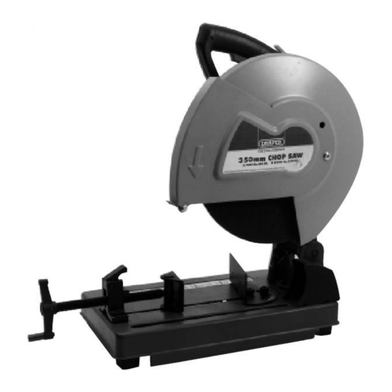
Parcourez en ligne ou téléchargez le pdf Manuel d'instructions pour {nom_de_la_catégorie} Draper CS14A. Draper CS14A 16 pages. 350mm chop saw
Également pour Draper CS14A : Manuel d'instructions (12 pages)

POWER SUPPLY
CONNECTING YOUR MACHINE TO THE POWER SUPPLY: (230V ONLY)
To eliminate the possibility of an electric shock your machine has been fitted with a BS approved, non
rewireable moulded plug and cable which incorporates a fuse, the value of which is indicated on the pin
face of the plug. Should the fuse need to be replaced an
same rating, marked thus
a replacement fuse cover is required, ensure it is of the same colour as that visible on the pin face of the
plug (i.e. red). Fuse covers are available from your Draper Tools stockist.
If the fitted plug is not suitable, it should be cut off and destroyed. *The end of the cable should now be
suitably prepared and the correct type of plug fitted. See below.
*WARNING:
A plug with bare flexible wires exposed is hazardous if engaged in a live power socket outlet.
WARNING THIS APPLIANCE MUST BE EARTHED.
Green and Yellow - Earth, Blue - Neutral, Brown - Live.
As these colours may not correspond with the coloured markings identifying the terminals in your plug,
proceed as follows.:
The wire which is coloured green and yellow must be connected to the terminal in the plug which is
marked with the letter 'E' or by the earth symbol
The wire which is coloured blue must be connected to the terminal which is marked with the letter 'N' or
coloured black or blue.
The wire which is coloured brown must be connected to the terminal which is marked with the letter 'L' or
coloured red or brown.
(N.B. Three phase machines must be connected by a qualified electrician).
WARNING: (110V ONLY)
Single phase 110 volt machines must be connected using the relevant coding and matching the colour of
the flexible cable to that of the plug. The procedure is as follows:
1. Connect green and yellow coloured core to the plug terminal marked letter 'E' earth symbol or
coloured green or green and yellow.
2. Connect brown coloured core to plug terminal marked letter 'L' (live).
3. Connect blue colour core to plug terminal marked letter 'N' (neutral).
EXTENSION LEAD CHART:
Extension lead sizes shown assure a voltage drop of not more than 5% at rated load of tool.
Ampere rating
(on Name plate)
Extension cable length
7.5m
15m
22.5m
30m
45m
WIRING DIAGRAM
. The fuse cover is detachable, never use the plug with the cover omitted. If
3
0.75
0.75
0.75
0.75
0.75
BLACK
SWITCH
BROWN
N.O.
approved BS1362 fuse must be used of the
or coloured green or green and yellow.
6
Wire Size mm
0.75
0.75
0.75
0.75
1.25
N.C.
- 4 -
10
2
1.0
1.0
1.0
1.25
1.5
BRUSH
ARMATURE
BLACK
13
1.25
1.5
1.5
1.5
2.5
