CommScope 6588291-2 Fiche d'instruction
Parcourez en ligne ou téléchargez le pdf Fiche d'instruction pour {nom_de_la_catégorie} CommScope 6588291-2. CommScope 6588291-2 17 pages. Fiber optic connector kits
Verify that Instruction Sheet (408- Series)
Pertains to Connector Kit Being Terminated
To Verify, Refer to Product Drawing for
Applicable Instruction Sheet at:
www.commscope.com
(Search by Connector Kit Part Number,
Click on the Part Number
, Click on Product Drawing)
Connector
Assembly
Termination
Cover G
1. INTRODUCTION
LightCrimp Plus SC simplex ber optic connector kits
are designed to be applied to ber optic cable. The
connectors are used with singlemode or multimode
125-- m m glass ber cable. These kits can be used
with any of the following media (paragraph of
assembly procedure is indicated next to media).
5.1. 900-mm Bare Bu ered Fiber
5.2. 250-mm Coated Fiber
5.3. 2.5- to 3.0- mm Loose Jacketed Cable
NOTE: Any jacketed cable used with SC connectors
must allow for the axial movement of the bu ered
ber in the jacket which occurs when the connector is
mated to another connector or device. Certain cable
constructions do not allow axial movement and are
not suitable for use with SC connectors. Refer to
Inspection Speci cation 129--1496 for a method of
determining whether a given cable construction allows
axial movement (result of the bu er pull test).
To obtain information on CommScope ® products, visit our website at
www.commscope.com/SupportCenter
LightCrimp Plus® SC Simplex
Fiber Optic Connector Kits
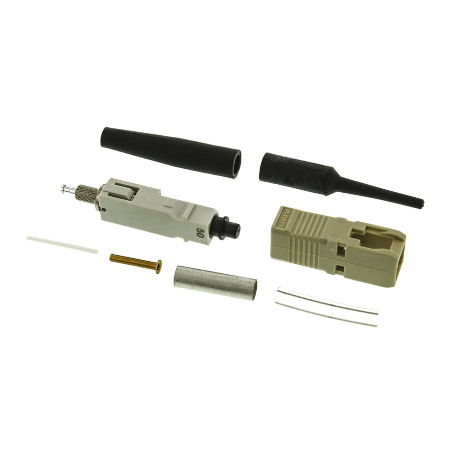
Crimp
Eyelet
Plunger
Dust Cap
Connector kit is shipped with these installed onto connector
assembly. Keep them in place until ready for assembly.
Figure 1
5.4. 900-mm Easy Strip or Semi- Tight Bu ered Fiber
Read these instructions thoroughly before assembling
the connector kits.
NOTE
Reasons for reissue of this instruction sheet are
provided in Section 6, REVISION SUMMARY.
2. DESCRIPTION
Each connector kit consists of a connector housing,
connector assembly, strain relief, inner eyelet, crimp
eyelet, and clear tubing. Each kit is also supplied with
a bare bu er boot and small tubing to compensate for
small diameter cable. Also included, assembled onto
the connector, are a termination cover for the ferrule
(front of connector) and a plunger dust cap for the
plunger (rear of connector).
©2017 CommScope, Inc.
All Rights Reserved
Strain
Relief
Inner
Eyelet
Small
Tubing
Connector
Housing
All numerical values in this instruction sheet are
in metric units. Dimensions are in millimeters.
i
Figures are for reference only and are not drawn
to scale.
(See Figure 1)
This product is covered by one or more U.S.
patents or their foreign equivalents. For patents, see
www.commscope.com/ProductPatent/ProductPatent.aspx
Instruction Sheet
408--4471
FEB 2017 Rev N
Bare Bu er
Boot
Clear
Tubing
1 of 17