CommScope 3X-C70B-3XR Instructions d'installation
Parcourez en ligne ou téléchargez le pdf Instructions d'installation pour {nom_de_la_catégorie} CommScope 3X-C70B-3XR. CommScope 3X-C70B-3XR 4 pages.
Micro AcCELLerator
3X-C70B-3XR
Bulletin 628043 • Revision A • March 2015 Page 1 of 4
GENERAL INFORMATION
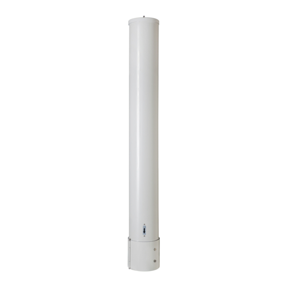
The 3X-C70B-3XR antenna (Figure 1) is a compact, tri-sector
antenna solution equipped with two hinged covers at the
base of the antennas which enable access to the RF and
AISG ports plus the mounting interface. Since mounting
locations and surfaces will vary, CommScope does not
provide the mounting bolts or associated hardware required
to properly install this antenna. It is the responsibility of
qualified personnel to determine the best method for
securely anchoring the base plate of the antenna to the
mounting surface.
After removing the antenna from its shipping container
carefully inspect it to ensure there is no shipping damage. If
the antenna is to be hoisted into position, ensure the lifting
eye bolt is correctly installed. Ensure the antenna is securely
held during hoisting to avoid rotation on the lifting eye bolt.
DO NOT remove the EYE BOLT after installation, otherwise
water ingress to antenna may occur.
Covers
Figure 1. 3X-C70B-3XR
Antennas
TM
Eye Bolt
Radome
Installation Instructions
CommScope Infrastructure Academy offers installation training.
INSTALLATION INSTRUCTIONS
1. Loosen the thumb screws (Figure 2), and open the
covers.
Thumb Screws
Cover
Figure 2. Hinged Covers
Cover
Thumb Screws
Base Plate
(continued on page 2)