ATI Audio DA2008-1 Manuel d'utilisation et d'entretien - Page 3
Parcourez en ligne ou téléchargez le pdf Manuel d'utilisation et d'entretien pour {nom_de_la_catégorie} ATI Audio DA2008-1. ATI Audio DA2008-1 7 pages. Dual 1x4 distribution amplifier

The inputs are protected from over-voltage inputs by clipping diodes. Dual
bypass capacitors protect the inputs against common mode RF pickup. Balanced
potentiometers (R15 and R16) allow setting a precise null for common mode hum
inputs.
OUTPUTS
Audio from the input buffer is AC coupled to the front panel level adjust
potentiometers.
The pot outputs are applied to the non-inverting input of the HI (in-phase) output
stage driver ICs. The ICs supply the first 10ma of output current directly, and
then complementary Class B output booster transistors take over. The unique,
wide bandwidth, high slew rate circuit design provides effective class AB
operation with minimal crossover distortion from a power output stage operating
true Class B with zero quiescent power dissipation.
The HI output bus is inverted and boosted to drive the LO output bus.
The HI and LO output buses of each channel are split into four individual
balanced outputs through 150 ohm build-out resistances. All outputs will tolerate
short circuits across the output or to the ground without damage. Up to two
outputs can be shorted with no significant reduction in headroom. Needless to
say, this is NOT the recommended mode of operation. Do not drive a LO output
into the grounded end of an unbalanced load. Drive single ended loads from
either the HI or LO output to ground. Up to 16 single-ended 600 ohm output
loads may be simultaneously driven by the DA2008-1.
The build-out resistors are split and heavily bypassed to prevent RF pickup on
the output lines from affecting operation of the DA. These bypasses will place a
very heavy load on the outputs under sustained sine wave operation above
20Khz and such operation may over-dissipate the 47 ohm build-out resistors—
don't do it!
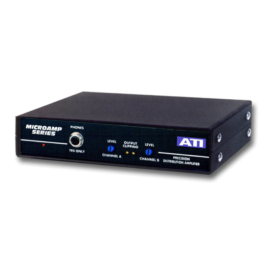
OUTPUT CLIPPING INDICATOR S
The differential input voltage of each HI output driver IC is monitored by a section
of A3. The differential voltage is under a few millivolts under linear operation;
however, if the output is driven to clipping the differential voltage rapidly
increases and is amplified to light the yellow OUTPUT CLIPPING LED. Conserve
power—try not to light the yellow LED.
ATI Audio Inc.
■ Tel: 856-626-3480
Fax: 856-504-0220
www.
audio.com
■
■
