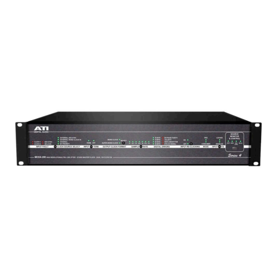
ATI Audio MCDA-208 Manuel d'utilisation et d'entretien - Page 7
Parcourez en ligne ou téléchargez le pdf Manuel d'utilisation et d'entretien pour {nom_de_la_catégorie} ATI Audio MCDA-208. ATI Audio MCDA-208 15 pages. Ultra-low-jitter studio master clock dual 1x4 aes/ebu distribution amplifier

FRONT PANEL DISPLAYS AND SWITCHES
POWER
Indicates that the MCDA is powered and power switch is on.
INPUT FAULT
Indicates loss of carrier on any of the four inputs, INPUT 1 (CLOCK 1), INPUT 2 (CLOCK 2),
AES SYNC-IN (AES SYNC) or WORD CLOCK INPUT (WCLK).
CLOCK SOURCE SELECT
Selects timing reference source for clock generator. Sequentially pressing the Clock Source
Select button selects from External AES Sync (AES SYNC-IN), External Word Clock Input
(WORD CLOCK INPUT), or Internal crystal reference. An additional button press illuminates the
BY PRIORITY LED and enables automatic priority selection of timing reference source in the
order: AES External Sync, External Word Clock In, or Internal. Selection is enabled only when
Source Monitor & Control WCLK LED is on.
INPUT TERM
Indicates whether the input termination is on or off for the source selected by the Source
Monitor & Control switch. Press the INPUT TERM button to toggle the setting. Settings are
individual for each source selected, and are memorized and retained through power outages.
OUTPUT CLOCK FORMAT
Indicates either Word Clock or Super Word Clock format available at outputs. Press the
SELECT button to toggle the setting. Enabled only when WCLK LED is on.
SAMPLE RATE
When Clock Source Select switch is set to INTERNAL and the WCLK LED is on, the SAMPLE
RATE switch selects the internal generator sample rate. For manual Word Clock sample rate
selection, set Source Monitor & Control to WCLK LED on. When the Clock Source switch is set
to EXTERNAL AES SYNC or EXTERNAL WORD CLOCK IN, the LEDs indicate the sample rate
of the external input from 32 kHz through 192 kHz.
WORD LENGTH
Indicates the Word Length of the input signal from 16 through 24 bit.
DIGITAL ERRORS
Indicates four error conditions encountered in digital signals as an aid to troubleshooting: Bi-
Phase/Parity, Validity, Non-Linear PCM and DTS-CD Signal.
7
!
"#$%&'()!"*+,*-!
!
