ATI Technologies SR-61 Manuel de remplacement - Page 8
Parcourez en ligne ou téléchargez le pdf Manuel de remplacement pour {nom_de_la_catégorie} ATI Technologies SR-61. ATI Technologies SR-61 11 pages. Robotic collision sensor switch replacement manual

Manual, Collision Sensor Switch Replacement,SR‑61
Document #9610‑60‑1014‑02
1.4.3 Replacement of Current Style Switch/Connector Block Assembly
1. Remove the mounting screw using a 2.5 mm hex key (see
2. Pull the connector block away from the Collision Sensor.
3. Discard the entire assembly.
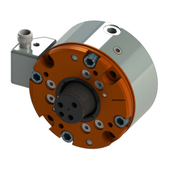
Figure 1.4—Removal of Switch/Connector Block Assembly from the Collision Sensor
4. Provide 5 to 15 psi of air to the unit at the port marked "P" (unless the unit is equipped with
preload springs).
5. Make sure the spring is on the sensor and the O‑ring is seated in the connector block. Press the
connector block assembly firmly against the body of the Collision Sensor while tightening the
screw to 64 in‑ozs. When tightened securely, the connector block assembly should rest parallel
to its mounting surface.
Figure 1.5—Switch/Connector Block Assembly installation
6. Perform switch adjustment per
Pinnacle Park • 1031 Goodworth Drive • Apex, NC 27539 USA • Tel: 919.772.0115 • Fax: 919.772.8259 • www.ati‑ia.com
9160-SENSOR-061-2
M3 Socket Head Cap Screw
Section 1.5.2—Current Style Switch
8
Figure
1.4).
O-Ring
Spring
Adjustment.
