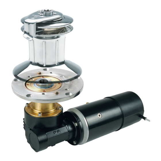
Andersen E1 Manuel du produit - Page 12
Parcourez en ligne ou téléchargez le pdf Manuel du produit pour {nom_de_la_catégorie} Andersen E1. Andersen E1 18 pages. Single speed electric motor unit, 12v & 24v
Également pour Andersen E1 : Manuel du produit (18 pages)

TROUBLESHOOTING
E1 IN-BUILT SYSTEM PROTECTION
The E1 Electric Motor Unit has a very high level of in-built system protection, via monitoring of
various operating parameters, its integrated controller and other protection/control componentry.
This functionality includes:
• Reverse polarity protection
• Mechanical overload protection
• System low voltage detection
• Thermal overload protection
• Continuous run time limiting
• Accidental start protection
REVERSE POLARITY PROTECTION
If the motor unit is inadvertently connected to the power system with reversed polarity the motor's
internal fuse will blow. The fuse will have to be replaced before the motor will start again.
To replace the fuse:
• Remove the cable ties that secure the control cable to the outside of motor cover.
• Remove the two screws from the end of the outer motor cover (using a #1 Phillips head
screw driver) - refer to picture below.
• Rotate the outer motor outer cover slightly and carefully pull the motor cover away from the
motor unit. Note: After the first 5mm (3/16") the O-ring will release the cover, there will be no
resistance the rest of the way, and very little force should be used so as not to damage the
internal wiring connections.
• When the outer cover is clear of the internal components, set it to one side so that there is
no tension on the internal control cable wires.
• Replace the 5A glass fuse, located on the PCB as shown below.
• Reassemble in reverse order. Make sure that the internal cables are not wedged between the
cover and internal components and again that no force should be required to replace the cover
until the O-ring is reached. Before pushing the cover on the final few millimetres over the O-ring,
make sure that the screw holes in the outer cover are aligned with the threaded rods inside.
Refer to picture below for threaded rod position.
Motor outer cover
attachment screws
E1 Single Speed Electric Motor Unit, 12V & 24V
To Suit Self-Tailing Winch Sizes 58,62
5A Glass Fuse
PCB location
Threaded rods for
motor outer cover
attachment screws
p12
