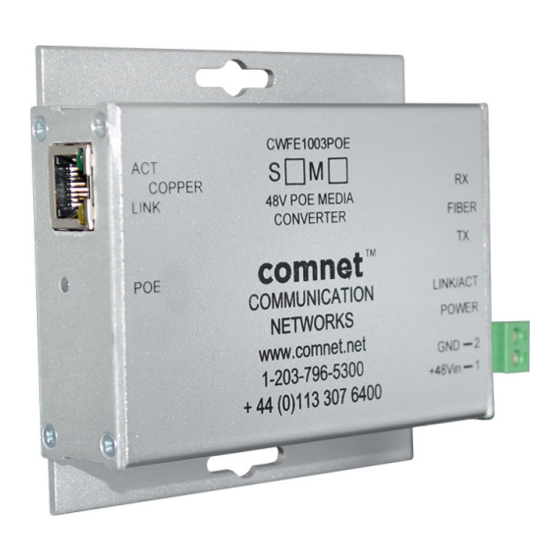
Comnet CNFE1004APOEM/M Manuel d'installation et d'utilisation - Page 8
Parcourez en ligne ou téléchargez le pdf Manuel d'installation et d'utilisation pour {nom_de_la_catégorie} Comnet CNFE1004APOEM/M. Comnet CNFE1004APOEM/M 9 pages. Cnfe100(x) poe series

INSTALLATION AND OPERATION MANUAL
FIGURE 13 – LED INDICATORS
FX LINK/ACT
GREEN
Fiber interface linked
(when lit or flashing)
OFF
Fiber interface not
linked.
FIGURE 14 – POSSIBLE ETHERNET CONFIGURATION
Ethernet IEEE 802.3 Network Element determined by user.
30W PoE
CAT5e/6 with
RJ-45 Connections
Remote Ethernet
IEEE802.3at PD
FIGURE 15 – POE PIN ASSIGNMENT
RJ-45 port supports IEEE802.3at
End-point:
Positive (VCC+): RJ45 pin 1, 2 or 4, 5
Negative (VCC-): RJ45 pin 3, 6 or 7,8
Data:
(1, 2, 3, 6)
TECH SUPPORT: 1.888.678.9427
POE
POWER
Power is being
Unit powered up
supplied by unit
Power not supplied
Unit powered down
by unit.
(No PoE device)
CNFE1003POEM-M
2 Multimode
Optical Fibers
CNFE100(X) POE SERIES
CNFE1003POEM-M
CAT5e/6 with
RJ-45 Connections
Ethernet IEEE 802.3
Network Element
INS_CNFE100(X) POE SERIES_REVA
04/25/13
PAGE 8
