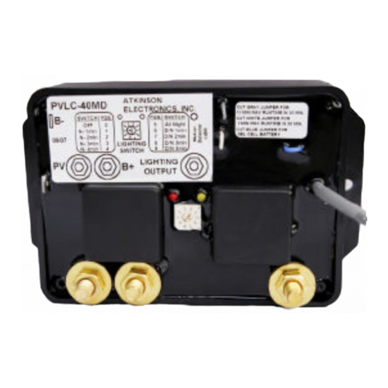
Atkinson Electronics PVLC-40MD Manuel de démarrage rapide - Page 2
Parcourez en ligne ou téléchargez le pdf Manuel de démarrage rapide pour {nom_de_la_catégorie} Atkinson Electronics PVLC-40MD. Atkinson Electronics PVLC-40MD 3 pages. Pv charge & lighting controller w/ motion sensor 40 amp

PV CHARGE & LIGHTING CONTROLLER W/ Motion Sensor 40 Amp
PVLC-40 TEMPERATURE THRESHOLDS
Below
08C
-
Between
0-58C
-
Between
5-108C -
Between
10-158C -
Between
15-308C -
Between
30-358C -
Between
35-408C -
Between
40-458C -
Above
458C
-
WIRING DIAGRAM - LIGHTING CONTROL APPLICATION
INSTALLATION AND STARTUP INSTRUCTIONS
1.
Connect the PV panel and lighting load negative wires to the negative battery post. Connect the PVLC-40MD Red (+) wire
to the Battery positive post and the PVLC-40MD Yellow wire to the PV panel + wire. Connect the Motion sensor to the
PVLC-40MD using the 3 wire 18awg cable, red to (+), black to (-), White to (NC), Jumper between (-) and other (C).
2.
Adjust the desired time range on the switch per PVLC-40MD switch lighting options.
3.
Now connect the PVLC-40MD Black wire to the battery negative terminal to power up the PVLC-40MD. Verify that the initial
battery voltage is greater than 11.3V or 22.6V, and PV voltage is greater than 16V or 32V.
4.
Twelve seconds after power up, the charge relay (red LED) will click the number of times per the switch position with "0"
being 10. If the switch did not get set to the desired position, disconnect the PVLC-40MD's negative battery wire and reset
switch to desired lighting operation and timing range. Reconnect the PVLC-40MD's negative battery wire and verify the
desired timing range. If the open circuit PV voltage is above 16V (32V) and the battery voltage is below the "turn on"
threshold (12.7VDC), then the PV charge relay will energize, charging the battery. Every 4 minutes the PV relay will drop-
out momentarily to test for the presence of adequate PV charge sunlight.
5.
To test the lighting function, wave your hand in front of the motion sensor. If lighting set for night only then disconnect the
PV Yellow wire, wave your hand in front of the motion sensor, the lighting relay (yellow LED) will turn on the lighting load.
6.
Now disconnect the PVLC-40MD black wire and reconnect the yellow PV wire, and then reconnect the black wire.
7.
Mount the PVLC-40MD securely with screws and coat the switch with silicone to insure that the entire module is waterproof.
Waterproof the electrical connections with silicone or grease.
Note:
The PVLC-40MD is powered by either the battery or PV voltage, which ever is greater. The charge relay is only powered
from the PV voltage and the lighting relay is only power by the battery voltage. If there is insufficient PV voltage when
powering up the PVLC-40MD, the charge relay will only click once after a 12 second delay. If there is sufficient PV
voltage( >16V/32V), then after a 12 second delay the PV relay will click out the switch position with "0" being 10 clicks,
it then checks the Battery voltage, if its below the "turn on" threshold, the charge relay energizes after a delay of 5
seconds. If battery voltage is above the turn on threshold, then it will wait until it drops below the threshold.
ATKINSON ELECTRONICS, INC.
Web Site: www.atkinsonelectronics.com
On @ 13.3V, Off @ 15.0V
On @ 13.3V, Off @ 14.8V
On @ 13.1V, Off @ 14.6V
On @ 12.9V, Off @ 14.4V
On @ 12.7V, Off @ 14.2V
On @ 12.7V, Off @ 14.0V
On @ 12.6V, Off @ 13.8V
On @ 12.6V, Off @ 13.6V
On @ 12.6V, Off @ 13.4V
PVLC-40 SWITCH - LIGHTING ADJUSTMENTS
Pos. "0"
-
Off
Pos. "1"
-
On for 1 min after sensor activation - night
Pos. "2"
-
On for 2 mins after sensor activation
Pos. "3"
-
On for 3 mins after sensor activation
Pos. "4"
-
On for 4 mins after sensor activation
Pos. "5"
-
On from dusk to dawn
Pos. "6"
-
On for 1 min after sensor activation - anytime
Pos. "7"
-
On for 2 mins after sensor activation
Pos. "8"
-
On for 3 mins after sensor activation
Pos. "9"
-
On for 4 mins after sensor activation
Distributed by:
PVLC-40MD
REV 09/07
