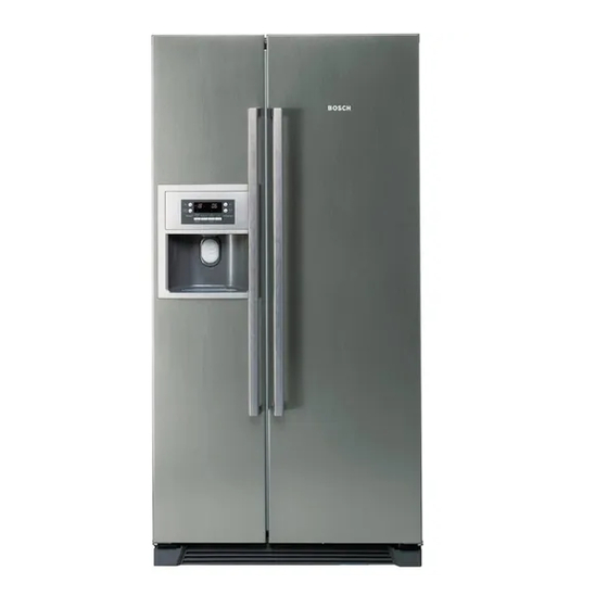
Bosch KAN58A40AU Instruction de réparation
Parcourez en ligne ou téléchargez le pdf Instruction de réparation pour {nom_de_la_catégorie} Bosch KAN58A40AU. Bosch KAN58A40AU 50 pages.
Également pour Bosch KAN58A40AU : Instruction de réparation (25 pages)

1
SAFETY ......................................................... 3
1.1
Safety instructions ............................................................... 3
1.2
Repair instructions .............................................................. 3
2
INSTALLATION ............................................. 4
3
OPERATION .................................................. 5
3.1
Freezer Set button ................................................................ 5
3.2
Refrigerator Set button ........................................................ 5
3.3
Super Cool button ................................................................ 5
3.4
Super Freeze button ............................................................ 5
3.5
Dispenser button .................................................................. 5
3.6
Ice Maker Lock button ......................................................... 5
3.7
Lock button ........................................................................... 6
3.8
Water Filter Reset button..................................................... 6
4
COMPONENTS ............................................. 7
4.1
Control module ..................................................................... 7
4.2
Ice maker .............................................................................. 7
4.3
Drinking water tank .............................................................. 8
4.4
Vario box ............................................................................... 9
4.5
Bar compartment flap ........................................................ 10
4.6
Freezer compartment fan .................................................. 11
5
FUNCTIONS ................................................ 12
5.1
Test programme ................................................................. 12
5.2
Cooling system .................................................................. 13
823_58300000113594_ara_en_u - 26.03.2015
R
E
P
A
I
R
I
N
S
T
R
U
C
T
I
O
N
R
E
P
A
I
R
I
N
S
T
R
U
C
T
I
O
N
R
E
P
A
I
R
I
N
S
T
R
U
C
T
I
O
N
Side by Side Daewoo
IWD
5.3
Waterflow ............................................................................. 14
5.4
Defrosting ............................................................................ 14
5.5
Manual defrosting ............................................................... 15
5.6
Door alarm ........................................................................... 16
5.7
Demo programme ............................................................... 16
5.8
Switching over temperature unit ....................................... 16
6
REPAIR ........................................................ 17
6.1
Opening the refrigeration circuit ....................................... 17
6.2
Leaks on intake side ........................................................... 17
6.3
Location of sensors ............................................................ 18
6.4
Sensor Values ..................................................................... 19
6.5
Sensor Values ..................................................................... 20
6.6
Sensor Values ..................................................................... 21
6.7
Changing the heater ........................................................... 22
6.8
Changing the thermal link .................................................. 25
6.9
Ice dispenser ....................................................................... 26
6.10
Changing the water supply flow rate ................................ 27
6.11
Removing the door handle ................................................. 28
6.12
Exchange display electronic .............................................. 29
6.13
Water discharge on the dispenser defective .................... 30
6.14
Arranging the doors ........................................................... 32
6.15
Attaching the replacement compressor ........................... 34
6.16
Connections on the replacement PC board ..................... 34
6.17
E or M on the rating plate ................................................... 35
6.18
Sanitisation ......................................................................... 36
Seite 1 von 50
