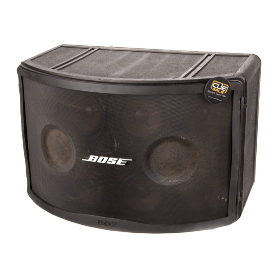
Bose 802 Series III Manuel d'entretien - Page 5
Parcourez en ligne ou téléchargez le pdf Manuel d'entretien pour {nom_de_la_catégorie} Bose 802 Series III. Bose 802 Series III 9 pages. Panaray 802 series iii loudspeaker
Également pour Bose 802 Series III : Manuel de l'utilisateur (4 pages)

1. Phase Test
1.1 Observing polarity, apply 9 VDC to the
input connector. Refer to the figure below.
1.2 All driver cones should move outward.
Referring to figure 1, rewire any driver that
moves inward.
1+
2+
2. Crossover Test
2.1 Connect a 0.5 Ohm resistor and amplifier
to the speaker input connector as shown in
the diagram below.
Amplifier
Volt meter
Speaker Output
-
+
-
0.5 Ohm
2.2 Apply a 2 Vrms signal to the speaker input
connector at the frequencies listed in the table
below.
2.3 Measure the voltage across the 0.5 Ohm
resistor comparing the results to the table
below. If the voltage is out of range, check the
crossover components and wiring.
Frequency
8 kHz
104 mVrns
12 kHz
77 mVrms
TEST PROCEDURES
Positive input
Negative input
Speaker
+
+
-
Min
Max
141 mVrms
120 mVrms
3. Rub and Tick Test
3.1 Apply a 10 Vrms, 10 Hz signal to the
speaker input connector.
3.2 No extraneous noises such as rubbing,
scraping or ticking should be heard.
Note: To distinguish between normal suspen-
sion noise and rubs or ticks, slightly displace
the cone of the driver with your fingers. If the
noise can be made to go away or get worse, it
is a rub or tick and the driver should be
replaced. If the noise stays the same, it is
normal suspension noise and the driver is
fine. Suspension noises will not be heard with
program material.
4. Air Leak Test
4.1 Apply a 15 Vrms, 65 Hz signal to the
speaker input connector.
4.2 Listen for air leaks around the drivers and
cabinet seam. Reposition or replace any
gasket found to leak. Repairs made to the
cabinet seam should not be visible from the
exterior of the speaker.
5. Sweep Test
5.1 Apply a 10 Vrms, 10 Hz signal to the
speaker input connector.
5.2 Sweep the signal generator from 10 Hz to
500 Hz.
5.3 Apply a 500 Hz, 5 Vrms signal to the
speaker input connector.
5.4 Sweep the signal generator from 500 Hz
to 5 kHz.
5.5 Listen for buzzes, rattles or other noises.
Redress any wire that buzzes; replace any
driver that is found to be defective.
Note: A whooshing noise from the port at its
resonance frequency of 50 Hz is acceptable.
5
