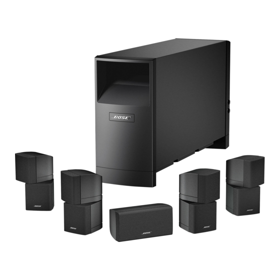
Bose Acoustimass 16 Series II Manuel du propriétaire - Page 7
Parcourez en ligne ou téléchargez le pdf Manuel du propriétaire pour {nom_de_la_catégorie} Bose Acoustimass 16 Series II. Bose Acoustimass 16 Series II 24 pages. Home entertainment speaker system
Également pour Bose Acoustimass 16 Series II : Manuel du propriétaire (44 pages), Manuel du propriétaire (33 pages), Manuel d'installation rapide (1 pages)

English
Español
Figure 3
Position options for your
Acoustimass module
Making the connections
Figure 4
Speaker cable connection
to an output jack on the
module and to the speaker
Français
Placing your Acoustimass
®
®
Bose
Acoustimass
speaker technology makes it difficult to locate the source of
low-frequency sound from this module. So feel free to hide it from view, and:
• Locate the module at the same end of the room as the television screen.
• Keep the module at least 2 feet (.6 m) from your TV set to prevent interference.
• To increase bass effects, turn the front opening toward a wall; turn it away from the wall to
decrease bass effects.
• Keep both the front opening and the ventilation grille on the bottom of the module at least
2 inches (5 cm) from any other surface.
• Do not block the ventilation grille located on the bottom of the module.
Impeding ventilation can cause a reduction in the bass-frequency output from the module.
Preferred
Alternate
Front opening
Only the Acoustimass module connects to your receiver. The small center front speaker and
cube speaker arrays connect directly to the Acoustimass module.
WARNING: Connecting the small speakers to a receiver can result in damage to your system
and possible electric shock.
Connecting speakers to the Acoustimass module
Insert the connector on each speaker cable into the jack on the module. Refer to the label on
each connector to match it to the proper jack.
Supplied
speaker cable
Matched labels
1. Use the supplied 20-foot (6.1 m) speaker cables for the three front speakers.
Insert the connectors, as labeled, into jacks on the module as follows
(Figure 5 on page 8).
• R goes into the jack labeled Right Front.
• C goes into the jack labeled Center Front.
• L goes into the gray jack labeled Left Front.
®
module
Ventilation grille
Cube speaker array
S
U
ETTING
P
Red collar
to red speaker terminal
7
