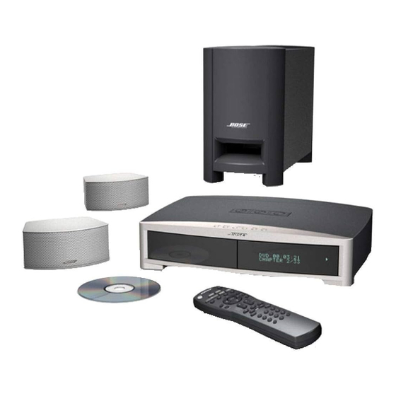
Bose 3-2-1 Manuel de dépannage - Page 19
Parcourez en ligne ou téléchargez le pdf Manuel de dépannage pour {nom_de_la_catégorie} Bose 3-2-1. Bose 3-2-1 28 pages. Home entertainment system
Également pour Bose 3-2-1 : Manuel du propriétaire (44 pages), Manuel d'installation rapide (1 pages)

6.6 RDS
European tuners contain additional components for the decoding of Radio Data System (RDS)
information. The LC72722 Radio Data System (RDS) decoder IC, U2200 [sheet 2, D6], is a
single-chip system IC that implements the signal processing required by both the European
RDS standard and US RDBS system. RDS/RDBS systems can send digital information over
the airwaves along with the standard FM signal by adding a digitally modulated 57 kHz sub-
carrier to the normal FM composite signal. The LC72722 includes a bandpass filter, demodula-
tor, synchronization, and error correction circuits. The input (pin 2) to the RDS IC comes from
Q2003 [sheet 1, C1], which buffers the FM composite signal at pin 23 of the LA1837. The time
base for the decoder is a crystal oscillator formed by the 4.332 MHz crystal, Y2200, the inverter
internal to the IC across pins 12 and 13, and the two shunt capacitors, C2205 and C2206.
Control of the RDS IC is achieved by using the same bus interface used for the PLL IC.
•
•
PS3
2
1 Series II Speaker System Theory of Operation
The following information describes the operation of the PS3
Note: Refer to the bass module amp and DSP schematic diagrams, 270921, for the following
information.
1. Components
•
•
The PS3
2
1 Series II Speaker System consists of:
•
•
•
The PS3
2
1 Series II Bass Module, 273031-*
•
Qty 2 Array Speakers, 255198-* or (Series II GS) 269990-*
•
Array Speaker Cable, 255123-* or (Series II GS) 269984-*
•
Line Cord 260082-*
•
Bass Module Interface Cable Assembly 269997-*
* Dash variants may vary.
The components above permit connection to the AV3
2. Bass Module Interface
Control and audio input to the bass module is by means of a 13-pin interface connector and
associated bass module to console cable. This interface provides up to 15 watts (average) of
unregulated DC power for operation of the connected console. The bass module is controlled
through a single-wire serial connection which utilizes the Smart Speaker protocol on a 4800
Baud, half-duplex, bi-directional connection. Audio from the console is transported to the bass
module via stereo analog and/or S/PDIF input. The analog and digital audio inputs may be
used in conjunction to allow the transport of multi-channel audio information. A separate MUTE
line is also provided to allow the console to immediately mute the audio output. Additionally,
there is a control line which completely powers down the DSP section of the bass module to
reduce power consumption, but it is not implemented in production.
THEORY OF OPERATION
19
•
•
2
1 Series II bass module.
•
•
2
1 Series II console.
