Bose PM8500 / PM8500N PM8250 Fiche technique - Page 4
Parcourez en ligne ou téléchargez le pdf Fiche technique pour {nom_de_la_catégorie} Bose PM8500 / PM8500N PM8250. Bose PM8500 / PM8500N PM8250 6 pages. Configurable professional power amplifier
Également pour Bose PM8500 / PM8500N PM8250 : Manuels d'installation et de sécurité (21 pages)
PowerMatch
configurable power amplifier
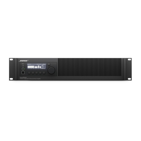
1. LED Indicators - Fault, Clip, Limit and Signal indication
2. LCD Display - Detailed graphical backlit display
3. Navigation Soft Key - Front panel interface navigation key
4. Rotary Encoder - Scroll to move LCD display cursor, push to select option
5. Menu Soft Keys (1 – 5) - Five pushbuttons mapping to onscreen selections
6. USB connector - Type B USB port for use with a PC running ControlSpace® Designer™ software
7. Front airflow vents - Filterless intake cooling for the amplifier
8. Front rack-mount ears - For use when securing into rack-mount enclosures
1. Analog Input connectors - Line-level balanced input connectors (+24 dBu max)
2. Fault-Notification Output - 3-pin normally open or normally closed contact closure fault connection (1A, 30 VDC max)
3. Ethernet network connector (network versions only) - RJ-45 connection supporting ControlSpace Designer software and Serial
over Ethernet communications
4. Rear airflow vents - Exhaust venting
5. Digital expansion slot cover - Supports optional ESPLink and digital audio network cards
6. Output connector - Loudspeaker connections (10 - 24 AWG)
7. AC Mains receptacle - Power cord connection (IEC 60320-C20 Inlet)
8. AC Mains retention clip - Secures the power cord to the amplifier
9. Power switch - ON/OFF AC power switch. Also serves as resettable circuit breaker
10. Rear rack-mount support tabs - Accommodates rear brackets for rear rail mounting
Bose Professional Systems Division
PM8500 / PM8500N
®
4
OF 6
p r o . B o s e . c o m