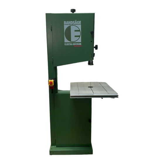
Elektra Beckum BAS 450 Manuel - Page 5
Parcourez en ligne ou téléchargez le pdf Manuel pour {nom_de_la_catégorie} Elektra Beckum BAS 450. Elektra Beckum BAS 450 19 pages. Guide de precision a trois rouleaux pour scie a ruban
Également pour Elektra Beckum BAS 450 : (français) Manuel (4 pages)

Application
Especially suitable for guiding the band saw blade where absolute precise cuts are required. The thrust bearing´s body
is hardened and precision groung, with Tungsten Carbide rims.
The advantages of the Precision Blade Guide over the Standard Blade Guide:
- improves versatility of the machine
- extended thrust bearing service life
- no tools required for thrust bearing setting and replacing
- suitable for machines with clockwise or counter-clockwise direction of rotation
User Responsibility
This accessory is designed and intended for use on band sawing machines and will perform in conformity with the
description contained in this manual. This accessory or any of its parts should not be altered from standard
specifications. The user of this accessory shall have the sole responsibility for any malfunction which results from
improper use or unauthorized modification from standard specifications, faulty maintenance, damage or improper repair
by anyone other than qualified persons approved by ELEKTRA BECKUM or their representatives.
Important
Before installing the Precision Blade Guide, the saw band guard must be
shortened by 45 mm, so the blade can still be changed when the Precision
Blade Guide is installed.
Loosen wing nut (135) and set blade guard ass'y (12) to lowest position, until
standard roller guide ass'y rests on the table. Remove the 4 raised countersunk
head screws (212) with Philips #2 screwdriver. Use a hacksaw to cut off
45 mm from the saw band guard as indicated in the drawing below.
Reinstall saw band guard.
Lowering the Table
Installing the Precision Blade Guide
requires lowering the band saw table.
Remove table completely from frame
and use drilling template provided to
mark position of the new holes
required. Drill four holes Ø 8.5 mm in
exact position and debur edges. With
the Precision Blade Guide installed
the maximum height of cut is reduced
by 15 mm.
Note! The carriage bolt M8x30,
located on the underside of the table,
must be replaced by the carriage
bolt M8x50 supplied (pos. 100 or
spacer bush 8x24).
This bolt serves as stop when tilting
the table back to the 90 position.
LINE OF CUT
5
GB
Drilling pattern
New holes
BAS 315/450
Existing holes
