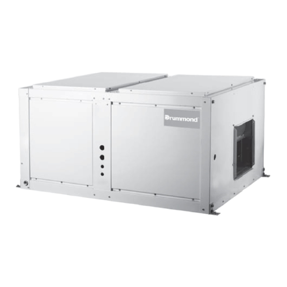
Drummond MOV-120CN1-D Manuel d'installation - Page 14
Parcourez en ligne ou téléchargez le pdf Manuel d'installation pour {nom_de_la_catégorie} Drummond MOV-120CN1-D. Drummond MOV-120CN1-D 16 pages. Split system cooling only, r-410a refrigerant
Également pour Drummond MOV-120CN1-D : Manuel du propriétaire (11 pages)

10.
MAINTENANCE
Regular maintenance
Some regular maintenance have been carried on by user,
includes: clean dust filter, clean casing, wash condenser and
replace a new belt, as well as do some test for the equipment.
filters
Motor mounting
One of the most critical aspects of an air handler installation is
the mounting of the motor, motor sheave, fan pulley and the
belts, and the adjustment of these items.
Motor sheave and fan pulley mounting and adjustment
The adjustable pitch sheave which is mounted on the motor
shaft controls the fan speed. To adjust the fan speed refer to
figure at right, proceed as followese adjustment of these
items.
a. Loosen the four set screw, item 1.
b. Rotate the adjustable sheave, item 2, to the desired
position.
c. Lock the adjustable sheave in place by tightening the set
screw, item 1.
NOTE:the adjustable sheave is not to be used to adjust belt
tension
MOTOR SHAFT
WARNING
BEFORE MAKING FAN ADJUSTMENTS, BE SURE THE
MAIN ELECTRICAL DISCONNECT SWITCH IS IN THE
"OFF" POSITION TO PREVENT POSSIBLE INJURY DUE
TO ACCIDENTAL OPERATION OF THE MOTOR.
Fig.10-1
motor
FAN BELT ALIGNMENT AND ADJUSTMENT
Place belt on the groove of the fan pulley and motor sheave
to obtain the approximate alignment and belt tension.
Remove the belt and align the fan pulley and motor sheave
using a straight edge,refer to figure.
When the pulley and sheave are properly aligned, re-install
belt. Do not force or pry the belt onto the pulley and sheave.
with the belt in place, adjust so that all the slack is on one side
of the drive. The belt should have from 3/4" to 1" of slack at 3
lbs pressure, refet to figure. Adjust the belt to this tension,
first, loosen the four screw as figure, then raise or lower the
swing base via the adjusting rods and nuts.
Refer to Fig.10-2, loose 4 nuts, and move the electric motor to
adjust belt tension.
The 4 nuts are used for factory
precision adjustment only,that
shall not be adjusted except
professional maintenance staff.
Belt tension is measured by belt tension indicator
Calculate the deflection, deflection=A/64.
Measure the belt deflection force, the force shuold be
between the values shown in Tab.10-1
Belt tension indicator applied to mid_center distance,
16mm defection per 1 metre fospan
4 nuts
Fig.10-2
Fig.10-3
A=315mm
Fig.10-4
Installation Manual
13
