Daikin R32 Split Series Manuel d'installation - Page 15

Parcourez en ligne ou téléchargez le pdf Manuel d'installation pour {nom_de_la_catégorie} Daikin R32 Split Series. Daikin R32 Split Series 16 pages. R32 split series
Également pour Daikin R32 Split Series : Manuel d'installation (17 pages), Manuel d'installation (16 pages), Manuel d'installation (16 pages), Manuel d'installation (16 pages), Manuel d'installation (17 pages), Manuel d'installation (16 pages), Manuel d'installation (20 pages), Manuel d'installation (14 pages), Manuel d'installation (14 pages), Manuel d'utilisation (16 pages), Manuel d'utilisation (16 pages), Manuel d'utilisation (8 pages), Manuel d'installation (17 pages), Manuel d'installation (20 pages), Manuel d'installation (20 pages), Manuel d'installation (16 pages), Manuel d'installation (16 pages), Manuel d'installation (14 pages), Manuel d'installation (14 pages), Manuel d'installation (16 pages), Manuel d'installation (17 pages), Manuel d'installation (20 pages), Manuel d'installation (13 pages)
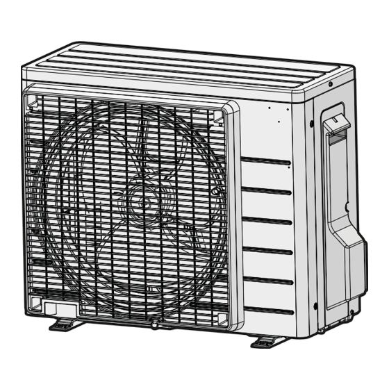
Daikin R32 Split Series Manuel d'installation
Symbol
S*T
S*RH
S*W, SW*
SA*, F1S
SR*, WLU
SS*
SHEET METAL
T*R
TC, TRC
V*, R*V
V*R
WRC
k
l
m
a
Liquid field piping
b
Gas field piping
c
Liquid stop valve
d
Gas stop valve
e
Liquid receiver
f
Filter
g
Electronic expansion valve
h
Muffler with filter
i
Capillary tube 1~3
j1
Outdoor temperature thermistor
j2
Heat exchanger thermistor
RXJ42+50A
R32 split series
3P512025-12X – 2021.12
Meaning
Thermostat
Humidity sensor
Operation switch
Surge arrester
Signal receiver
Selector switch
Terminal strip fixed plate
Transformer
Transmitter
Varistor
Diode bridge, Insulated-gate
bipolar transistor (IGBT) power
module
Wireless remote controller
j2
i1
i2
i3
j3
o
n
Symbol
X*
X*M
Y*E
Y*R, Y*S
Z*C
ZF, Z*F
14.2

Piping diagram

14.2.1

Piping diagram: Outdoor unit

PED categories of equipment:
▪ High pressure switch: category IV,
▪ Compressor: category II;
▪ Other equipment: art. 4§3.
j1
h
g
f
m
e
m
c
d
j3
Discharge pipe thermistor
k
Heat exchanger
l
4-way valve (ON: heating)
m
Muffler
n
Compressor
o
Accumulator
HPS
High pressure switch (automatic reset)
M
Propeller fan
Refrigerant flow: cooling
Refrigerant flow: heating
14 Technical data
Meaning
Terminal
Terminal strip (block)
Electronic expansion valve coil
Reversing solenoid valve coil
Ferrite core
Noise filter
a
b
Installation manual
15