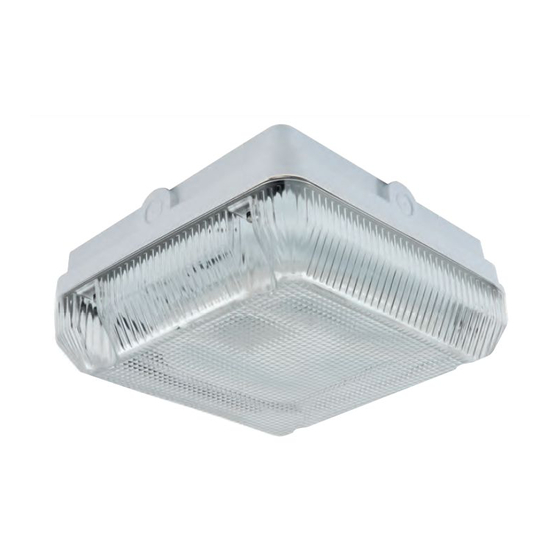
Ansell Astro AA16 Instructions d'installation
Parcourez en ligne ou téléchargez le pdf Instructions d'installation pour {nom_de_la_catégorie} Ansell Astro AA16. Ansell Astro AA16 3 pages. Alpha bulkhead, 16watt 2d / 28watt 2d

General Installation Instructions
These instructions should be read carefully prior to any installation and retained after completion for further
reference and maintenance. Please give these instructions to the building owner/occupier after installation.
Important Safety
1. Before installation, maintenance or lamp replacement, ensure that the mains supply to the luminaire is switched off and the circuit
supply fuses are removed or the circuit breaker is turned off.
2. It is recommended that only a qualified electrical contractor carries out the installation of this luminaire and that the luminaire is
installed in compliance with the current edition of the IEE Wiring Regulations.
3. The person carrying out the installation is to check and verify that the total load on the circuit, including that of this luminaire does
not exceed the rating of the circuit cable, fuse or circuit breaker.
4. Where a luminaire incorporates discharge control gear (inductive load), the circuit capacity and ratings require careful sizing to
avoid nuisance tripping of the protective device used in the installation.
5. Where applicable, careful consideration should be taken during installation to ensure that all fixings and/or suspensions are of a
suitable size for the luminaire being installed.
Ratings
1. All luminaires are manufactured & tested in compliance with the requirement contained within BS EN 60598 and are CE marked.
2. All luminaires carrying the "F" mark are suitable for installation on to normal flammable surfaces.
3. All luminaires that are of Class 1 construction and that are marked accordingly, MUST be earthed.
4. All luminaires are designed to operate at 230Volts AC -2%/+10% = 225Volts to 253Volts. Do not operate outside these voltages.
5. All luminaires are only suitable for applications within their rated Ingress Protection limits as stated.
-------------------------------------------------------------------------------------------------------------------------------------------------------------------------------
Installation
Remove the diffuser from the base by releasing the captive screws around the edge of the luminaire.
•
Remove the CFL-DD lamp supplied by pulling away from the gear tray (grip lamp by the plastic base), care should be taken
•
not to use undue force and not to pull using the glass of the lamp.
Loosen but do not remove the gear tray retaining screws.
•
Adjust the position of the gear tray to align the hole in the keyhole slots with the retaining screws, and remove the gear tray
•
from the base.
Select a suitable cable entry point by drilling into the base.
•
Position and fix the base to a suitable solid surface using screws supplied, rubber washers or sealant should be applied
•
around the screw heads to reduce water ingress if the luminaire is to be mounted externally, or in damp or wet locations.
Pass supply cable into the luminaire through previously selected entry ensuring that a cable gland, grommet or sealing
•
compound is used to maintain the IP rating of the luminaire.
Terminate the cable into the terminal block mounted on the underside of the gear tray ensuring correct polarity is observed
•
and that the luminaire is earthed.
Replace the gear tray by aligning the holes in the keyhole slots with the retaining screws on the base, adjust the gear tray
•
so the retaining screws are now aligned with the holes of the keyhole slots, and retighten the retaining screws.
Plug in and replace the lamp into the lamp holder on the gear tray.
•
Re-fit the diffuser, do not over-tighten the screws.
•
Restore the mains supply, switch on and test for satisfactory operation.
•
Installation of Emergency Luminaires – Additional Instructions to above
Connect as follows:-
For a switched Maintained operation, connect as above. For a continuous Maintained operation, install a continuous live to the permanent
live terminal and fit a link between live and permanent live.
Connect the battery lead to the positive battery terminal. This is not connected for safety reasons during transit.
•
Restore power supply, switch on and test operation. A 24 hour period is required for battery to charge fully.
•
Warning
Failure to comply with these instructions may result in irreparable damage to the emergency control gear.
•
This product must not be modified in any way as this will negate any Safety approvals, and may render the product inoperable or unsafe.
•
The product must be installed in accordance with the instructions.
-------------------------------------------------------------------------------------------------------------------------------------------------------------------------------
Page No. 1
Description – Alpha Bulkhead, 16Watt 2D / 28Watt 2D
Installation Instructions
®
Luminaire Code(s) –
PERMANANT LIVE
LIVE
NEUTRAL
EARTH
www.anselluk.com
AA16 / AA28 & M3
(L)
BROWN OR RED (continuous)
(L)
BROWN OR RED (switched)
(N)
BLUE OR BLACK
GREEN / YELLOW
Issue Date: pd 20070413
