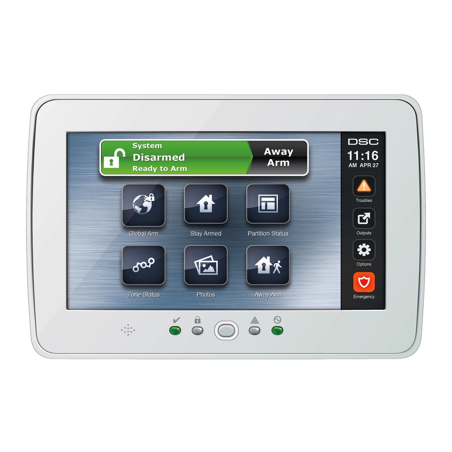
DSC PowerSeries PTK5507 Manuel d'instructions d'installation - Page 3
Parcourez en ligne ou téléchargez le pdf Manuel d'instructions d'installation pour {nom_de_la_catégorie} DSC PowerSeries PTK5507. DSC PowerSeries PTK5507 8 pages. V1.0 power series

3. Connect the four Keybus wires from the control panel
(green, yellow, black, and red) to the keypad terminals.
Refer to Figure 4.
Figure 4 - Wiring
PTK5507
NOT USED
GRN
YEL
BLK
RED
Applying Power
Once all wiring is complete, and the equipment is secured to
the building structure with at least two screws, apply power
to the control panel:
alarm shop
1. Connect the battery leads to the battery.
2. Connect the AC transformer.
3. Connect telecommunication network.
For more information on control panel power specifications,
see the control panel Installation Manual.
CAUTION: Route all the wiring according to the local codes and
regulations.
Programming the Keypad
There are sev-
Toggle Option
eral program-
ming options
1 _ _ 4 _ _ _ _
available for
the
keypad.
These are described below. Programming the keypad is sim-
ilar to programming the rest of the system. When you are in
the keypad programming sections, the keypad will display
which options are turned on. To turn an option on or off,
press the number corresponding to the option on the number
pad. The numbers of the options that are currently turned
ON will be displayed. For example, if options 1 and 4 are
on, the display will look like the diagram shown.
For information on programming the rest of your security
system, please refer to your system's Installation Manual.
NOTE: Do not enable keypad blanking (panel programming,
section 016, option 3). If keypad blanking is enabled, the panel
will stop sending out the status and the keypad status will be
inaccurate.
Enrolling the Keypad
The keypad will need to be assigned to a partition and slot if
supervision or keypad zones are being used. Keypad
assignments and keypad option programming must be done
at each keypad individually.
The 1st digit of keypad assignment is used to determine
partition assignment (1 to 8). If partitioning is not used,
enter [1]. For Global Keypads, enter [0].
The 2nd digit of keypad assignment is used to determine
slot assignment for keypad supervision. Each keypad will be
assigned a different slot number from 1 to 8.
Enter the following at each keypad installed on the system:
1. Enter Installer Programming by pressing Options, Installer
Menu [Installer Code], then Keypad Mode Prog.
2. Press [000] for keypad programming.
3. Press [0] for Partition and Slot Assignment.
4. Enter the 1st digit (0 to 8 for partition assignment).
5. Enter the 2nd digit (1 to 8 for slot assignment supervision).
6. Press the [#] key twice to exit programming.
7. After assigning all keypads, perform a supervisory reset by
entering Options, Installer Menu, [Installer's Code], [902],
and waiting for 60 seconds.
8. Press the [#] key to exit programming after 60 seconds.
Programming Labels
1. Enter Options, Installer Menu [Installer Code], then Label
Programming.
2. Select the desired Label to Program.
3. Using the keyboard on the screen, enter the new label and
press save when complete.
Broadcasting LCD Labels
All LCD programming is done per keypad. If more than one
LCD keypad is present on the system, labels programmed at
one keypad can be broadcast to all other LCD keypads. Per-
form the following procedure in order to broadcast labels:
Step 1 - Program one LCD keypad completely.
Step 2 - Make sure all LCD keypads are connected to the Keybus.
Step 3 - Enter keypad programming by pressing Options,
Installer Menu [Installer Code], Keypad Mode Prog, then enter
section [,] [998] [,] at the keypad that was programmed.
The keypad will now broadcast all the information pro-
grammed to all the other LCD keypads on the system.
Step 4 - When the keypad is finished press the [#] key to exit.
ASCII Characters
Changing Backlight (Brightness Level)
1. Press Options, Keypad Config, then Backlight.
2. Use slide bar to adjust brightness to desired setting.
3. Press the Back or Home button.
Changing the Buzzer Level
1. Press Options, Keypad Config, then Buzzer Control.
2. Use slide bar to adjust buzzer to desired setting.
3. Press the Back or Home button.
Entering Calibration Mode
1. Press Options, Keypad Config, then Calibration.
2. Press the cross hairs on the screen to complete calibration.
NOTE: Calibration mode can also be entered by pressing and
holding the home button for 3 seconds.
Changing the Background Image
1. Press Options, Installer Menu [Installer Code], Keypad Pro-
gramming, then Background Image.
2. Select image to use image from SD card as background
image.
3. To exit, press Back or Home button.
