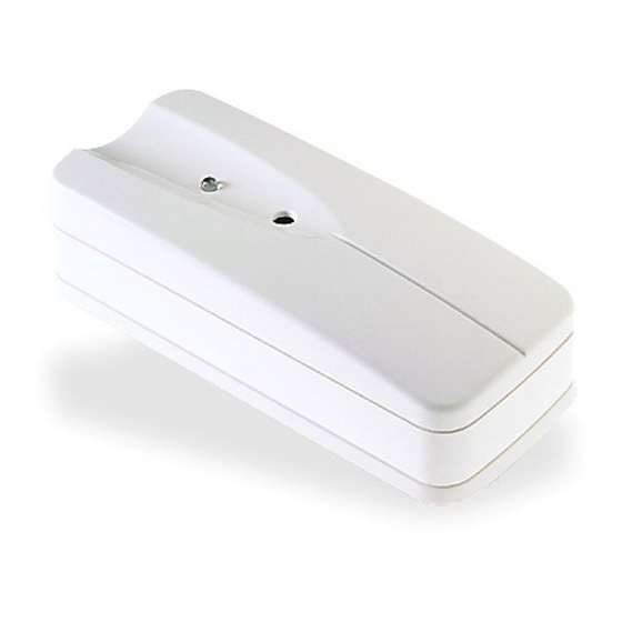
DSC WLS912 Instructions d'installation
Parcourez en ligne ou téléchargez le pdf Instructions d'installation pour {nom_de_la_catégorie} DSC WLS912. DSC WLS912 2 pages. Glassbreak detector
Également pour DSC WLS912 : Manuels et instructions d'installation (2 pages)

Mounting the Detector
Once you have found a location that is within range
of the receiver, you can mount the WLS912.
1.
Remove the mounting plate from the detector.
2.
At the selected mounting location, place the
mounting plate on the wall (with the tab facing
down, or to the right), or on the ceiling. Mark
the screw locations. Wall anchors should be
used for all screw locations.
3.
Secure the backplate to the wall.
4.
Slide the detector onto its backplate.
5.
Repeat the installation test using the AFT–100
tester to confirm proper operation.
FCC Compliance Statement
CAUTION: Changes or modifications not expressly approved by Digital Security Controls Ltd. could void your authority
to use this equipment.
This equipment generates and uses radio frequency energy and if not installed and used properly, in strict accordance with
the manufacturer's instructions, may cause interference to radio and television reception. It has been type tested and found
to comply with the limits for Class B device in accordance with the specifications in Subpart "B" of Part 15 of FCC Rules,
which are designed to provide reasonable protection against such interference in any residential installation. However, there
is no guarantee that interference will not occur in a particular installation. If this equipment does cause interference to tele-
vision or radio reception, which can be determined by turning the equipment off and on, the user is encouraged to try to
correct the interference by one or more of the following measures:
• Re-orient the receiving antenna
• Relocate the alarm control with respect to the receiver
• Move the alarm control away from the receiver
• Connect the alarm control into a different outlet so that alarm control and receiver are on different circuits.
If necessary, the user should consult the dealer or an experienced radio/television technician for additional suggestions. The
user may find the following booklet prepared by the FCC helpful: "How to Identify and Resolve Radio/Television Interfer-
ence Problems". This booklet is available from the U.S. Government Printing Office, Washington, D.C. 20402, Stock # 004-
000-00345-4.
Limited Warranty
Digital Security Controls Ltd. warrants that for a period of twelve months from the date of purchase, the product shall be
free of defects in material and workmanship under normal use and that in fulfilment of any breach of such warranty, Digital
Security Controls Ltd. shall, at its option, repair or replace the defective equipment upon return of the equipment to its repair
depot. This warranty applies only to defects in parts and workmanship and not to damage incurred in shipping or handling,
or damage due to causes beyond control of Digital Security Controls Ltd. such as lightning, excessive voltage, mechanical
shock, water damage, or damage arising out of abuse, alteration or improper application of the equipment.
The foregoing warranty shall apply only to the original buyer, and is and shall be in lieu of any and all other warranties,
whether express or implied and of all other obligations or liabilities on the part of Digital Security Controls Ltd. This war-
ranty contains the entire warranty. Digital Security Controls Ltd. neither assumes, nor authorizes any other person purporting
to act on its behalf to modify or to change this warranty, nor to assume for it any other warranty or liability concerning this
product.
In no event shall Digital Security Controls Ltd. be liable for any direct, indirect or consequential damages, loss of anticipated
profits, loss of time or any other losses incurred by the buyer in connection with the purchase, installation or operation or
failure of this product.
© 1999 Digital Security Controls Ltd.
1645 Flint Road, Downsview, Ontario, Canada M3J 2J6
Tel. (416) 665-8460 • Fax (416) 665-7498 • Technical support line 1-800-387-3630
www.dscgrp.com
Printed in Canada 29003922 R002
WLS912
Glassbreak Detector
INSTALLATION INSTRUCTIONS
The WLS912 is a battery-operated glassbreak sensor, designed to detect the sound
produced by the shattering of framed glass. Equipped with an RF transmitter, the
WLS912 establishes a supervised, one–way communications link with the system
controller.
The WLS912 uses Dynamic Signal Processing* to provide accurate detection of
plate, laminated, wired and tempered glass types, while rejecting common false
alarm sounds.
*Protected under US Patent 5,675,320
Specifications
Operating Voltage ................. 4.5V (three "AA" Alkaline Batteries)
o
Operating Temperature .......... 0
C - 50
Operating Humidity ............... 5% – 95% RH, non-condensing
Maximum detection range
Glass Type
Thickness
Minimum Glass
Size (L X W)
Plate/
1/8" – 1/4"
12" X 12"
Tempered
3 – 6mm
30cm X 30cm
Wired/
1/4"
18"X18"
Laminated
6mm
46cmX46cm
Battery Guidelines and Installation
Before installing batteries, please note the following guidelines:
•
The detector is designed to work with Eveready Alkaline Energizer "AA"
batteries. Do not install any other type. "No-name" or generic brand
batteries may not provide the best quality and dependability.
•
Always replace all three batteries at the same time.
•
When disposing of used batteries, follow the instructions and precautions
printed on the batteries. Many cities and communities have collection sites or
services for used household batteries. Contact your municipal offices for
information on the disposal of used batteries.
To install batteries:
1.
Remove the detector from its mounting plate:
If unmounted, hold the detector by its sides and push down
on the top end of the mounting plate, as shown at right.
If mounted, press the detector in the direction shown below.
o
o
o
C (32
F- 122
F)
Level 1 Setting
Level 2 Setting
20ft
10ft
6m
3m
20ft
DO NOT USE
6m
