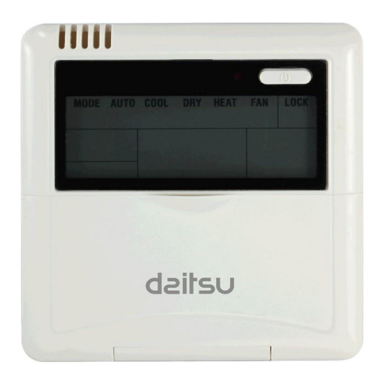
Daitsu RTD-75-UT Manuel d'entretien - Page 9
Parcourez en ligne ou téléchargez le pdf Manuel d'entretien pour {nom_de_la_catégorie} Daitsu RTD-75-UT. Daitsu RTD-75-UT 11 pages. Wire remote control

Accessories
Item
Wired controller
Wood mounting screw
Mounting screw
Installation manual
Owner's manual
5P terminal group
Installation screw
Preparing at site
Item
5-core shield cable
Switch box
Wiring tube
Wiring principle
When it is necessary to use the wired controller, please follow the label of A/B/C/D/E to
connect the wired controller. And the other side of the signal wire should be connected with
main PCB board well. A is anode, and B is cathode. C is +5V. D is GND and E is RUN.
Installation:
Confirm the installed location of wired controller, before install the wired controller. If install
it on the wall without electric switch box, the hole for 5P-terminal of wired controller is
necessary.
Dimension of rear cover as following picture (Unit: mm):
Quantity
1
\
3
M4×20 (For mounting on the wall)
3
M4×25 (For mounting on the electrical switch box)
1
\
1
\
\
\
\
For fixing terminal.
Quantity
1
RVVP-05mm
1
\
1
Insulating sleeve and tightening screw.
Remarks
Remarks
2
×5. The longest wire is 30m.
