DSC HS2064 E Manuel de l'utilisateur - Page 7
Parcourez en ligne ou téléchargez le pdf Manuel de l'utilisateur pour {nom_de_la_catégorie} DSC HS2064 E. DSC HS2064 E 7 pages. Alarm panel

Chapter 3.0 The PowerSeries Neo Security System
3.0 The PowerSeries Neo Security System
Your PowerSeries Neo has been designed to provide you with the greatest possible flexibility and
convenience. Read this manual carefully and have your installer instruct you on how to operate your
system and which features have been implemented in your system. All users of this system should
be equally instructed in its use. Fill out section "System Information" with all of your zone inform-
ation and access codes and store this manual in a safe place for future reference.
Note: The PowerSeries Neo security system includes specific false alarm reduction features and is
classified in accordance with ANSI/ SIA CP-01-2010 Control Panel Standard - Features for False
Alarm Reduction. Please consult your installer for further information regarding the false alarm
reduction features built into your system as all are not covered in this manual.
3.1 General System Operation
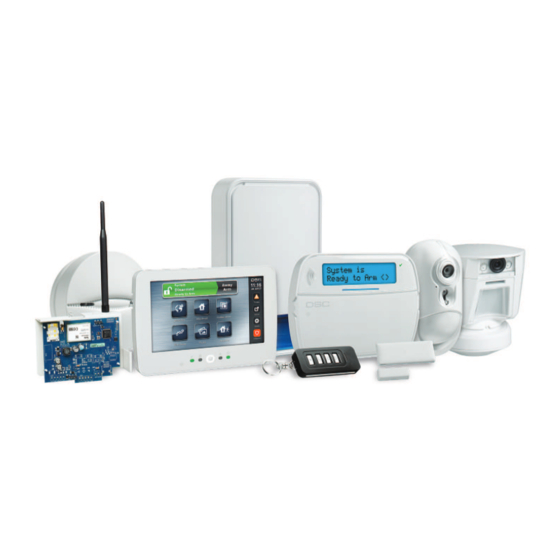
Your security system is made up of a PowerSeries Neo control panel, one or more keypads and vari-
ous sensors and detectors. The control panel will be mounted out of the way in a utility closet or in
a basement. The metal cabinet contains the system electronics, fuses and standby battery.
All the keypads have an audible indicator and command entry keys. LED keypads have a group of
zone and system status lights. LCD keypads have an alphanumeric liquid crystal display (LCD).
The keypad is used to send commands to the system and to display the current system status. The
keypad(s) will be mounted in a convenient location inside the protected premises close to the
entry/exit door(s). The security system has several zones of area protection and each of these zones
is connected to one or more sensors (motion detectors, glassbreak detectors, door contacts, etc.). A
sensor in alarm is indicated by the corresponding zone lights flashing on an LED keypad or by mes-
sages on the LCD keypad.
Note: Only the installer or service professional shall have access to the control panel.
3.2 Testing Your System
Tests all system keypad LEDs, keypad sounders, bells and/or sirens. To ensure that your system con-
tinues to function as intended, you must test your system weekly.
IMPORTANT: For UL HOME HEALTH CARE listed applications the system shall also be
tested weekly without AC power. To remove AC from the control unit, remove the screw from the
restraining tab of the plug in adapter and remove the adapter from AC outlet. After completing the
test of the unit using only the battery backup source, reconnect the plug in adapter and attach the
screw through the restraining tab so that the adapter is securely attached to the outlet.
IMPORTANT: Should your system fail to function properly, contact your installation company.
IMPORTANT: All smoke detectors must be tested by your smoke detector installer once per year.
To Perform a Keypad and Siren Test
1.
From the Ready state press [*][6] and enter the [Master Code]
to access User Functions.
2.
Press [04] or use the scroll keys to navigate to System Test and
press [*]. The system activates all keypad sounders, bells/sirens
and keypad LEDs for two seconds.
3.
To go back to the Ready state press [#].
Note: If your system has PIR cameras enrolled, two images from each PIR camera are sent to the
monitoring station during a system test.
- 7 -
LCD Display
Press (*) for <>
User Functions
Press (*) for <>
System Test
