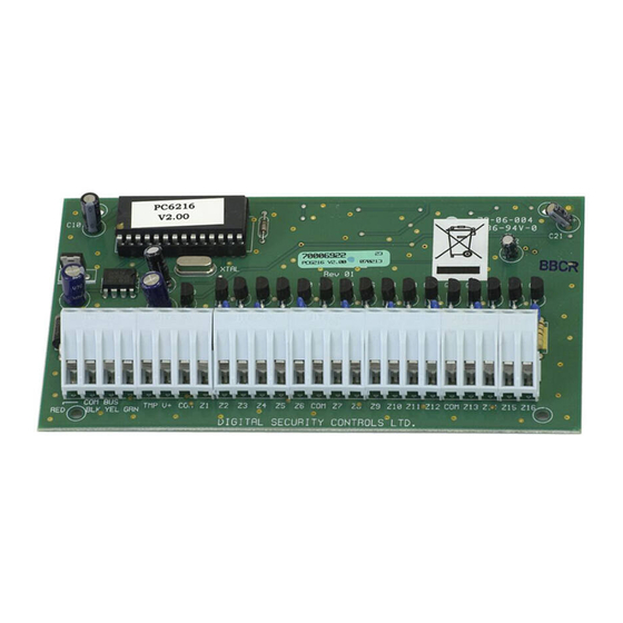
DSC PC6216 Instructions d'installation
Parcourez en ligne ou téléchargez le pdf Instructions d'installation pour {nom_de_la_catégorie} DSC PC6216. DSC PC6216 4 pages. Output module
Également pour DSC PC6216 : Instructions d'installation (4 pages)

PC6216
Output Module
1. Introduction
The PC6216 is an output module with 16 programmable outputs.
2. Specifications
• 16 output low current module, 12V, 50mA max. each,
power drawn from Combus
• Up to 9 modules per system
• 9 modules programmable as alarm or zone annunciators
• Each of the 9 modules programmable for all 16 outputs;
available output options determined by the control panel
software version
• Connects to control panel via 4-wire Combus
• Nominal current draw of 30mA
• Tamper contact input
Compatible Cabinets
• PC4003C
• PC4006C
• PC4001C/4002C
3. Installing the PC6216
3.1
Unpacking
The PC6216 package should include the following parts:
• One PC6216 circuit board
• 4 plastic stand-offs
3.2
Mounting
The PC6216 should be located inside a compatible cabinet,
mounted in a dry, secure location. Preferably, it should be
placed at a convenient distance from the connected devices.
Perform the following steps to mount the unit:
1. Press the four plastic stand-offs through the mounting
holes at back of the cabinet.
2. Secure the cabinet to the wall in the desired location. Use
appropriate wall anchors when securing the cabinet to
drywall, plaster, concrete, brick or other surfaces.
Please refer to the System Installation Manual for information on limitations regarding product
use and function and information on the limitations as to liability of the manufacturer.
Installation Instructions
3. Press the circuit board into the plastic stand-offs to secure
the module to the cabinet.
Once the unit is mounted, wiring may be completed.
3.3
Installation and Wiring
Before beginning to wire the unit, ensure that all power (AC
transformer and battery) is disconnected from the control panel.
Perform the following steps to complete wiring:
1. Connect the four Combus wires to the PC6216. Connect
the red, black, yellow and green Combus wires to the RED,
BLK, YEL and GRN terminals, respectively.
2. Complete all output wiring as illustrated below:
The latching output will cause the status of all 16
programmable outputs to latch during a Combus reset. To
do this, connect as shown above.
3. Connect the external tamper switch, if used.
Consult the wiring diagrams for further information.
