Attero Tech unD32 BoB Manuel de l'utilisateur - Page 7
Parcourez en ligne ou téléchargez le pdf Manuel de l'utilisateur pour {nom_de_la_catégorie} Attero Tech unD32 BoB. Attero Tech unD32 BoB 19 pages. 32 channel dante break out box

unD32 BoB
User Manual
2 – Installation
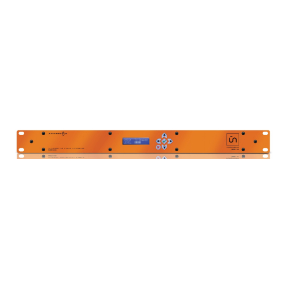
The unD32 comes ready to be mounted into a standard 1RU rack. The rack mount tabs are built in to the front panel of
the unit (rack screws are not supplied).
2.1 – Power Connection
Attach the provided power supply to power connector on the back of the unD32. The use the provided AC power cable
to connect the power supply to standard AC outlet. There is no "on" switch so the unit will power up as soon as the
power connection is made.
*Note: It is recommended to attach the power supply to the unD32 first, then connect the power cord to the power
supply and finally, plug the cable into the AC outlet.
2.2 – Network Connections
There are two configurations for network connectivity. Each is listed below. Select the configuration that best fits your
application.
2.2.1 – Single Network Connection
This type of network connection is probably the most common and uses a single Ethernet cable connecting the unD32
to the Ethernet switch that is providing the Dante network to the area of the facility where the unD32 is installed. The
Ethernet cable can be plugged into any of the three ports on the unD32.
*Note: This is the default configuration and the unD32 should require no configuration changes to work in this mode.
However, if problems occur when using this type of network topology, make sure the unD32 is configured for switch
mode (refer to Dante Controller User's Guide for information on how to do this).
The unused ports of the unD32 may be used to connect other devices to the Dante network if required. However, as
the unD32 acts as a switch, devices connected in this must count the unD32 as a switch hop.
2.2.2 – Redundant Network Connection
This type of network connection relies on the Dante network in the area of the facility where the unD32 is to be
installed being provided by two completely separate networks. This type of network topology provides redundancy
through duplication to each of the devices units connected to the network. To use the unD32 in such a system, connect
the primary port to a switch on the primary network and then connect the secondary port to a switch on the secondary
network. When using this type of network topology please make sure the unD32 is configured for redundant mode
(refer to Dante Controller User's Guide for information on how to do this).
*Note: It is recommended before using redundancy mode that the Audinate documentation on redundancy be reviewed
to ensure the full implication of its use on both the network design and the system design are understood. Problems will
result when redundancy mode is enabled on the unD32 if the audio networks are not designed and setup correctly to
work in this manner.
In this mode, the local port can be used as a control port as it can access the device regardless of whether the unD32 is
operating on its primary or secondary interface (only one of which will be active for audio transfers at any one time).
© Attero Tech LLC 2015
Page 6
614-00012 Rev 02
