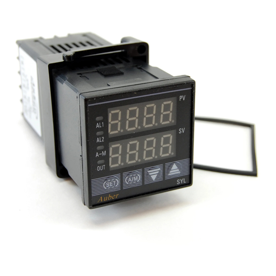
Auber SYL-2342P Manuel d'instruction - Page 6
Parcourez en ligne ou téléchargez le pdf Manuel d'instruction pour {nom_de_la_catégorie} Auber SYL-2342P. Auber SYL-2342P 8 pages. Pid temperature controller

AUBER INSTRUMENTS
A=1, direct action control mode for cooling control.
B=0, without alarm suppressing when turned on or when set point changes.
B=1, alarm suppressing at power up or set point changes.
C=0, display unit in ºC.
C=1, display unit in ºF.
The factory setting is A=0, B=1, C=1 (heating, with alarm suppression, display
in Fahrenheit). Therefore,
COOL=0X1+1X2+1X8=10
To change from Fahrenheit to Celsius display, set COOL=2
4.15 Input digital filter "FILt"
If measurement input fluctuates due to noise, then a digital filter can be used
to smooth the input. "FILt" may be configured in the range of 0 to 20.
Stronger filtering increases the stability of the readout display, but causes
more delay in the response to change in temperature. FILt=0 disables the
filter.
4.16 Manual and Automatic Mode Selection "A-M"
Parameter A-M is for selecting automatic or manual control mode.
A-M=0, manual control mode
A-M=1, automatic control mode (either PID or On/off control)
A-M=2, automatic control mode, in this state manual operation is prohibited
This parameter functions differently for controllers with the ramp/soak function
(see supplemental manual for details).
4.17 Lock up the settings, field parameter "EP" and parameter "LocK"
To prevent the operator from changing the settings by accident, you can lock
the parameter settings after initial setup. You can select which parameter can
be viewed or changed by assigning one of the field parameters to it. Up to 8
parameters can be assigned into field parameter EP1-EP8. The field
parameter can be set to any parameter listed in Table 2, except parameter EP
itself. When LocK is set to 0, 1, 2, and so on, only parameters or setting
values of program defined in an EP can be displayed. This function can speed
up parameter modification and prevent critical parameters (like input, output
parameters) from being modified.
If the number of field parameters is less than 8, then define the first unused
parameter as none. For example, if only ALM1 and ALM2 need to be modified
by field operators, the parameter EP can be set as following:
LocK=0, EP1=ALM1, EP2=ALM2, EP3=nonE.
In this case, the controller will ignore the field parameters from EP4 to EP8. If
field parameters are not needed after the instrument is initially adjusted,
simply set EP1 to nonE.
Lock code 0, 1 and 2 will give the operator limited privileges to change some
of the parameters that can be viewed. Table 5 shows the privileges
associated with each lock code.
Table 5. LocK parameter
LocK value
SV Adjustment
0
Yes
1
Yes
2
No
3 and up
No
808
Note: to limit the control temperature range instead of completely locking it,
please refer to section 4.9.
2011.02
EP1-8 Adjustment Other parameters
Yes
Locked
No
Locked
Yes
Locked
No
Locked
unlocked
5. Wiring examples
5.1 Controlling the load directly with internal relay
1
13 14
6
2
7
3
8
SYL-2342
+
4
9
-
5
10
TC
Figure 6. SYL-2342 or SYL-2342P control the heater directly by the
internal relay of the controller. The heater must consume less current than
the internal relay's maximum rating (7A at 240VAC and 10A at 120VAC).
5.2 Controlling the load via external contactor
Alarm1
Alarm2
12V
DC
1
13
14
6
2
7
3
8
SYL-2342
+
4
9
-
5
10
TC
Figure 7. SYL-2342 or SYL-2342P with thermocouple input and external
relay output. This is a typical wiring for oven and kiln.
Using the external contactor allows users to control higher power loads than
the internal relay can handle. It is also easy to service. If the contacts of the
relay wear out, it is more economical to replace them than to repair the
controller. In this example, we assume the coil voltage of the contactor is the
same as the voltage of the controller power supply. The voltage of power
supply for alarm is 12V DC. Note: You don't have to wire or set the alarm
to control the temperature. It is just to show how the alarm can be wired.
5.3 Controlling the load via SSR
Alarm1 12V DC
1
13 14
6
2
7
+
SSR
R
3
8
SYL-2352
-
R
4
9
5
10
W
Figure 8. SYL-2352 or SYL-2352P with RTD input. This is a typical wiring for
controlling the temperature of a tank of liquid with high precision.
The RTD sensor can offer accuracy within a fraction of a degree . The SSR
allows the heater to be switched at higher frequency for better stability. It also
has longer life time than the electromechanical relay. A proper heat sink is
needed when the SSR switches >8A of current. For wiring a 240V heater,
please see 5.4.
WWW.AUBERINS.COM
Heater
Fuse
L
N
120VAC
Heater
Contactor
Fuse
L
N
Heater
3
2
4
1
Fuse
120VAC
L
N
120VAC
P6/8
