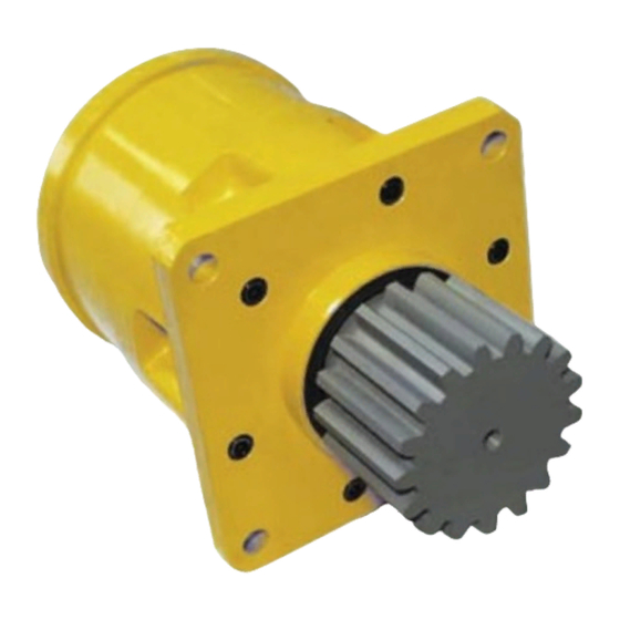
IMPORTANT: All Power Wheel units and kits are shipped with a nameplate that includes the Auburn Gear part number and order code as shown.
Power Wheel
Example:
ORDER CODE: 6WB13156C
PART NO.: 6000236
SERIAL NO.: 143434
AUBURN, IN U.S.A.
In addition to the nameplate, Power Wheel drives are stamped with an identification number which appears on the cover or hub flange as shown.
6000236-A-4-9
Example:
When ordering parts, the information included on the nameplate or the stamped identification number is necessary to accurately identify the drive
and obtain the correct replacement parts. Once this information has been obtained, contact Auburn Gear for the appropriate parts list.
STEP 1
Slide the coupling (1) from splines on input shaft (2).
STEP 2
Position the assembly upright on face of spindle (3).
STEP 3
Remove the disengage cover (31) if necessary.
STEP 4
Remove eight bolts (29) and the large cover (28) from the unit. The thrust
washer (25) and the disengage plunger (26) usually remain attached to the
large cover (28) when it is removed. Remove thrust washer (25), disengage
plunger (26) and "O" ring (27) from the large cover (28).
STEP 5
Remove primary sun gear (24) from end of input shaft (2).
STEP 6
Remove the primary carrier assembly (22).
STEP 7
Remove the secondary carrier assembly (21).
STEP 8
Remove the input shaft (2) from spindle (3). Remove the retaining rings (17),
washers (18), and disengage spring (19) from input shaft (2) only if replace-
ment is required.
STEP 1
Press new bearing cups (7 & 12) in each side of the hub (11). It is recom-
mended that bearing cups (7 & 12) and cones (6 & 13) be replaced in sets.
STEP 2
Assemble bearing cone (6) into cup (7) at seal end of hub (11) and press a
new seal (5) into hub (11). Install boot seal (4) on hub (11) if unit is so
equipped.
STEP 3
Position spindle (3) upright on bench. Lubricate lips of seal (5) and lower hub
(11) onto spindle (3). Hub (11) should be centered as it is lowered over spindle
(3) to prevent seal damage.
STEP 4
Assemble bearing cone (13) over spindle (3). Press bearing cone (13) over
spindle bearing journal using press and cylindrical bearing cone driver 598E.
Press bearing cone (13) down until rollers just touch cup (12). Take care to
avoid pressing cone (13) too far. N
598E over splined end of spindle (3) on the edge of bearing cone (13) and
drive into place with hammer or mallet. If this method is used, care must be
taken to avoid damage to bearing cone and spindle.
IDENTIFICATION
®
DISASSEMBLY OF POWER WHEEL
ASSEMBLY OF POWER WHEEL
: If a press is not available, place tool
OTE
STEP 9
One tab of lock washer (15) will be engaged in slot of bearing nut (16); bend
back to release. Remove the bearing nut (16), lock washer (15) and thrust
washer (14). N
: A special locknut wrench, 596Z, is required for the removal
OTE
of the bearing locknut. Contact Auburn Gear for procurement of wrench and
other service tools.
STEP 10
Bolt spindle drive tool, 598FF, to ring gear (20). Grade 8 bolts should be used.
Drive spindle (3) from hub (11) by turning center bolt of spindle drive tool.
Care should be taken to avoid damaging splines and threads on spindle.
N
: Bearing cone (13) has been designed with a press fit with respect to
OTE
spindle (3). Considerable force will be required to remove cone from spindle.
STEP 11
Remove spindle drive tool from ring gear (20).
STEP 12
Remove the 12 bolts (9) and washers (10) from hub (11) and remove ring
gear (20). It may be necessary to strike ring gear (20) with a rubber mallet to
loosen from hub (11).
STEP 13
Remove the boot seal (4) and oil seal (5) and bearing cones (6 & 13) from
hub (11). Inspect bearing cups (7 & 12) in position and remove only if
replacement is required.
STEP 5
Install thrust washer (14) with tab in keyway of spindle and bearing nut (16).
DO NOT install lock washer (15) at this time.
STEP 6
Clean mating surfaces and apply a bead of silicone sealant to face of hub (11)
that mates with ring gear (20). See instructions on sealant package. Hub (11)
is attached to ring gear (20) with 12 3/8-24 grade 8 hex head cap screws (9)
and flat washers (10). Torque cap screws to 52 - 60 lb.-ft. (70 - 81 Nm).
STEP 7
Place spindle drive tool, 598FF, over spindle (3) and bolt or pin to ring gear
(20). Make sure center bolt of drive tool is not touching spindle and is
prevented from rotating by jam nuts provided on tool.
STEP 8
Check initial rolling torque by installing a lb.-in. torque wrench (arm or dial
type) on center nut of spindle drive tool and turning hub (11) slowly and
steadily with the torque wrench. Note mean torque. An initial bearing torque of
greater than 52 lb.-in. with boot seal installed or 46 lb.-in. without boot seal
means that the cone (13) was pressed on too tightly in step 4. In this case,
back off bearing cone (13) by pressing spindle (3) out of cone (13) until initial
preload is relieved. See step 10 of disassembly procedure.
2

