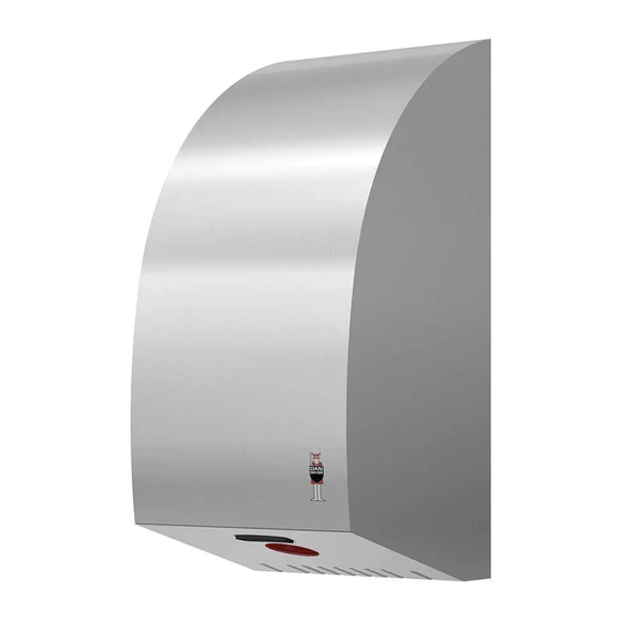
DAN DRYER 5-709818-002880 Manuel de l'utilisateur - Page 5
Parcourez en ligne ou téléchargez le pdf Manuel de l'utilisateur pour {nom_de_la_catégorie} DAN DRYER 5-709818-002880. DAN DRYER 5-709818-002880 6 pages. Stainless design turbo hand dryer

TROUBLESHOOTING AND CORRECTIVE ACTIONS
SYMPTOM
CORRECTIVE ACTION: NEW HAND DRYER
The dryer does not run
•
Check power supply to the product and ensure the
connections at the terminal block are made properly.
The dryer cycles by itself and
•
Make sure nothing is obstructing the IR-sensor activa-
runs constantly
tion area.
•
If problem persists, check the recommended installa-
tion height.
The dryer is very loud and
•
Ensure power supply is correct
does not run for a complete
•
If the timer is damaged, replace both timer and sensor
cycle
Hand dryer runs randomly
•
Check timer and sensor. Replace if required.
and stops before the cycle is
finished
The hand dryer runs, but the
•
Ensure the voltage is correct.
airspeed is low
•
Check setting of potentiomenter for air speed adjust-
ment (see page 7).
SYMPTOM
CORRECTIVE ACTION: USED HAND DRYER
Hand dryer does not start
•
Check power supply to the product and ensure the
connections at the terminal block are made properly.
IR-sensor only detects motion
•
Make sure nothing is obstructing the IR-sensor.
when hands are placed really
•
Clean sensor. If the problem persists, disconnect the-
close to the hand dryer
power and remove the cabinet, taking suitable precau-
tion to avoid schock hazard.
•
Carefully adjust sensor range (see paragraph on this
subject).
•
If the problem persists, replace sensor and timer.
The dryer gets hot, but there is
•
Disconnect the power. Remove the cover and disas-
no air stream
semble the blower/fan unit.
The dryer blows only cold air
•
Disconnect the power.
during a full cycle
•
Remove the cover and disassemble the blower/fan
unit.
•
Check the heating element thermostate for open
circuit.
•
Check the heating element for defects. Replace defect
heating element.
Hand dryer does not run
•
Check carbon brushes. Replace if they are worn or
smoothly
damaged. If no faults are detected, replace motor.
8
RESERVEDELE, TURBO DESIGN
Kabinet
Nylon-b¯sning til hul til kabelindgang
TrÊkaflastningsb¯jle
KlemmerÊkke
Jordskrue
St¯ddÊmper
BlÊserhus, top
Gummipakning til blÊserhus (stor)
Motor, 700 W
Gummipakning til blÊserhus (lille)
Varmelegeme, 900 W
UdblÊsningsstuds
Beslag til sensor
Sensor
OphÊng til blÊserhus
Bagplade
Potentiometer
Beslag til potentiometer
Timer
BlÊserhus, bund
Kabinetskrue (2 stk.)
Unbrakon¯gle til kabinetskruer
PARTS LIST
12
13
14
No. Description
1
Housing
2
Nylon bushing for cable inlet hole
3
Cable clamp
4
Terminal block
5
Earthing screw
6
Shock absorber
7
Blower housing - upper part
8
Rubber gasket for blower housing
(large)
9
Motor, 700W
10
Rubber gasket for blower housing
(small)
11
Heating element, 900W
12
Outlet branch
15
16
17
18
19
20
21
22
No. Description
13
Gasket for sensor
14
Sensor
15
Bracket for blower housing
16
Backplate
17
Potentiometer
18
Bracket for potentiometer
19
Timer
20
Blower housing – lower part
21
Housing screws (2 pcs.)
22
Allen key for housing screws
9
