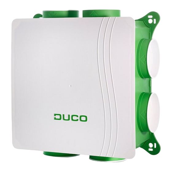
Duco DucoBox Silent 325 Manuel d'installation - Page 6
Parcourez en ligne ou téléchargez le pdf Manuel d'installation pour {nom_de_la_catégorie} Duco DucoBox Silent 325. Duco DucoBox Silent 325 16 pages.
Également pour Duco DucoBox Silent 325 : Manuel de démarrage rapide (16 pages), Manuel d'installation (12 pages), Manuel d'installation (16 pages)

ENGLISH
RF (wireless communication)
RF components have a maximum free-field range of 350 metres� This distan-
ce will be much less in a building because of obstacles� Therefor you will need
to allow for features such as walls, concrete and metal� All slave components
(except those which are battery powered) also act as repeaters� Signals from
components that are unable to make a (strong) connection with the master
component are forwarded automatically via no more than one other non-bat-
tery-powered component (= hop point)� Please refer to information sheet
RF communication (L8000018) at www�duco�eu for further information�
Wired (cabled communication)
Wired components can be daisy-chained (= recommended)� This means that a
separate cable will not be required for each component� A single central power
supply can be used�
The cable required is a 5 x 0�75 mm² data cable� We strongly advise using a shiel-
ded cable� This is to prevent any interference that may affect the data communi-
cation� Any Tronic grilles will be supplied with a 5 x 0�25 mm² cable which can be
connected via a splicing terminal block�
05 Additional control options
05.A Boxsensors
Boxsensors can be built into a DucoBox Silent Connect and provide
CO
and/or humidity measurement in an air duct� A DucoBox Silent
2
Connect can contain a maximum of one CO
Boxsensor� If the living room (CO
(humidity measurement) are connected to the same duct/zone, the
two Boxsensors can be clipped together�
Fitting + connecting Boxsensor
Twist the Boxsensor(s) into the desired duct in the box
1
until the Boxsensor clicks home�
Connect the Boxsensors to one of the two connectors
2
provided on the DucoBox Silent Connect PCB�
Settings
The CO
and RH setpoint can be changed using the Duco Network
2
Control Tool� See www�duco�eu for more information�
6
L2000641 Installation guide for DucoBox Silent (Revision G | 17.07.2019)
and one Humidity
2
measurement) and bathroom
2
DUCO RF
Power supply
Wiring
Frequency
Maximum distance
Maximum number
of components
DUCO WIRED
Power supply
Wiring
Maximum distance
Maximum number
of components
1
CO
2
RH
CLICK
230 VAC
1,5 mm²
868 Mhz
350 m, free field (less
through obstacles)
Up to 25 wireless
components in a
single system
24 VDC
5 x 0�75 mm²
(5 x 0�25 mm² from Tronic
grilles)
up to 300 m
Up to 99 wired
components in a
single system
2
CLICK
CLICK
RH
CO2
DucoBox
