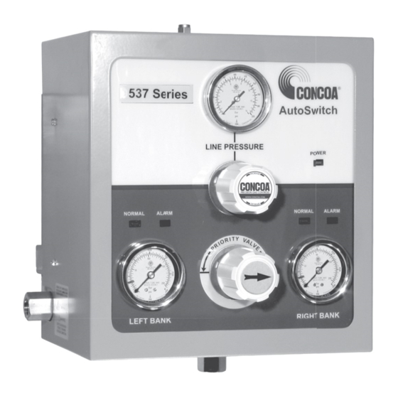
Concoa 537 Series Manuel d'installation et d'utilisation - Page 9
Parcourez en ligne ou téléchargez le pdf Manuel d'installation et d'utilisation pour {nom_de_la_catégorie} Concoa 537 Series. Concoa 537 Series 20 pages. Autoswitch systems
Également pour Concoa 537 Series : Manuel d'installation et d'utilisation (17 pages)

Follow the steps below:
1. Move the power switch to the off position (down) on the 529 5298 or 529 5300 remote alarm. Disconnect
the power source to the 529 5298 or 529 5300 remote alarm.
2. Locate the connector assembly. Slide all of the cable components onto the cable as shown below.
3. Solder the four wires of one end of the cable to the pins of the plug. Please note the wire colors associated
to PIN 1, PIN 2, PIN 3, and PIN 4 (see below for pin layout).
4. Push the locking nut onto the plug.
5. Push the cable retainer into the plug until it snaps in.
6. Clamp the cable retainer tabs with pliers until the tabs lock in place on the outside cable insulation.
7. Stretch the cable cover over the cable retainer and plug. For the connector to be water resistant, the cable
cover must cover the holes on the plug.
8. Plug the cable into the male connector located on the bottom of the switchover system.
9. On the other end of the cable, strip each end of the four wires about 1/8" and insert the wire into the
appropriate terminal. Follow the wiring assignments shown in the table below to wire the autoswitch to the
remote alarm. Tighten the remote alarm terminal block screw using a small, flat-tip screwdriver.
TB1-19 TB1-20 TB2-1 TB2-2 TB2-3 TB2-4 TB2-5 TB2-6 TB2-7 TB2-8 TB2-9 TB2-10
SYS 1
PIN 1
PIN 2
SYS 2
PIN 1
PIN 2
SYS 3
SYS 4
Cable Retainer Tabs
Cable
Cable
Cover
Retainer
Plug
PIN 3
PIN 4
PIN 3
Locking
Nut
Triangle Indicates Pin 1
Figure 6. Pin Connections
PIN 4
PIN 3
PIN 4
Plug
PIN 1
PIN 3
PIN 4
PIN 1
PIN 2
PIN 2
9
