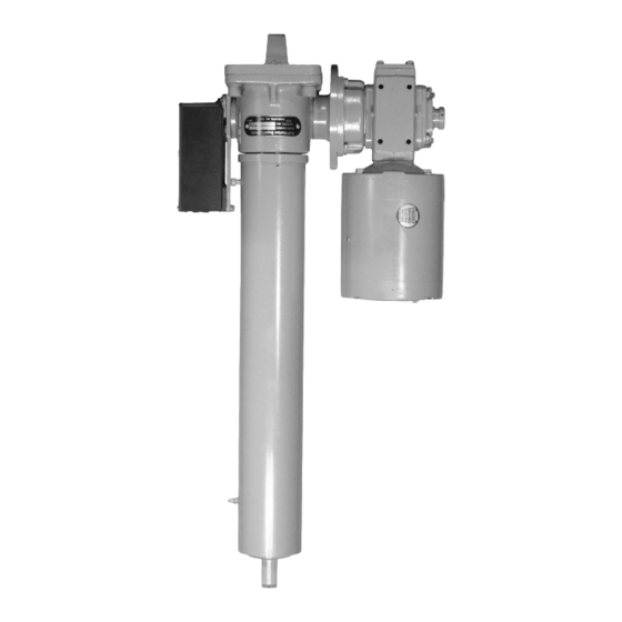
Duff-Norton SuperCylinder Series Instructions d'installation, d'utilisation et d'entretien - Page 2
Parcourez en ligne ou téléchargez le pdf Instructions d'installation, d'utilisation et d'entretien pour {nom_de_la_catégorie} Duff-Norton SuperCylinder Series. Duff-Norton SuperCylinder Series 12 pages. Linear actuators

General Introduction ................................................................................................... 3
1-1. General ............................................................................................................... 3
1-2. Applications ........................................................................................................ 3
1-3. Specifications ..................................................................................................... 3
1-4. Important Precautions ........................................................................................ 3
1-5. Warranty and Warranty Repair ........................................................................... 3
Section II
Installation .................................................................................................................. 4
2-1. Inspection ........................................................................................................... 4
2-2. Clevis Pins .......................................................................................................... 4
2-3. Orientation .......................................................................................................... 4
2-4. Vent plugs ........................................................................................................... 4
2-5. Wiring.................................................................................................................. 4
2-6. Limit Switch Adjustment ..................................................................................... 4
Section III
Lubrication .................................................................................................................. 5
3-1. Lubrication .......................................................................................................... 5
3-2. Motor Reducer Lubrication ................................................................................. 5
3-3. Motor and Reducer Bearings .............................................................................. 5
3-4. Clevis Pins .......................................................................................................... 5
Section IV
Maintenance ............................................................................................................... 6
4-1. Disassembly (Refer to Figure 5-1) ...................................................................... 6
4-2. Screw & Tube Disassembly ................................................................................ 6
4-3. Gear Removal ..................................................................................................... 6
4-4. Screw and Nut Inspection ................................................................................... 6
Table 1 ........................................................................................................................ 6
4-5. Lifting Nut Removal ............................................................................................ 6
Table 2 ........................................................................................................................ 7
4-6. Cleaning ............................................................................................................. 7
4-7. Inspection (Refer to Figure 5-1) .......................................................................... 7
4-8. Assembly (Refer to Figure 5-1) ........................................................................... 7
Section V
Illustrated Parts List .................................................................................................... 8
5-1. General ............................................................................................................... 8
Figure 5-1. Exploded Illustration for Duff-Norton
SuperCylinder Series .................................................................................................. 9
Figure 5-2. Exploded Illustration of Duff-Norton
SuperCylinder Parallel Configuation ......................................................................... 10
Figure 5-3. Exploded Illustration of Duff-Norton
SuperCylinder Right Angle Configuration ................................................................. 11
2
Contents
