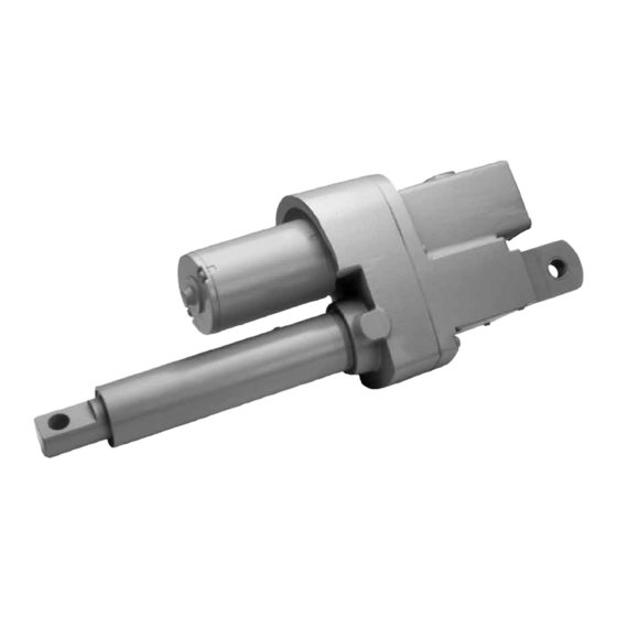
Duff-Norton TracMaster 6415 Series Manuel - Page 2
Parcourez en ligne ou téléchargez le pdf Manuel pour {nom_de_la_catégorie} Duff-Norton TracMaster 6415 Series. Duff-Norton TracMaster 6415 Series 16 pages.

Section I
1-1.
General .......................................................................................................................................3
1-2.
Industrial Use Only ....................................................................................................................3
1-3.
Factory Preparation ....................................................................................................................3
1-4.
Warranty and Warranty Repair ...................................................................................................3
1-5.
Specifications .............................................................................................................................3
Table 1-1.
6415 Series DC Actuator Specifications ....................................................................................3
Table 1-2.
6415 Series DC Super Pac Actuator Duty Cycle .......................................................................3
1-6.
Dimensions and Specifications ..................................................................................................4
Figure 1-1.
LSPD-5415 DC Technical Illustration .......................................................................................4
Section II
2-1.
Installation Procedures ...............................................................................................................5
2-2.
Limit Switch Adjustment ...........................................................................................................5
2-3.
Post-installation Procedures .......................................................................................................5
2-5.
Digital Position Indicator ...........................................................................................................6
Section III
3-1.
Operational Procedures ..............................................................................................................6
Section IV
4-1.
Lubrication .................................................................................................................................7
4-2.
Required Tools ...........................................................................................................................7
4-3.
General Procedures ....................................................................................................................7
4-4.
Disassembly ...............................................................................................................................7
4-5.
Assembly....................................................................................................................................8
Figure 4-1.
Potentiometer Nut and Washer Illustration ................................................................................4
Section V
Parts List for 6415 AC Actuator ...............................................................................................12
Figure 5-1.
Exploded Parts Illustration 6415 Series AC Actuator ..............................................................13
Section VI
6-1.
Brake Alignment ......................................................................................................................14
Figure 6-1A. Brake Spring, Motor and Pinion Coupling Alignment ............................................................14
Figure 6-1B. Brake Spring, Motor and Pinion Coupling Alignment ............................................................14
6-2.
Limit Switch Wiring Diagram .................................................................................................14
Figure 6-2.
Limit Switch Wiring Diagram, 6415 Series AC Actuator ........................................................14
6-3.
Limit Switch Assembly ............................................................................................................14
Figure 6-3.
Limit Switch Assembly, 6415 Series AC Actuator ..................................................................14
Contents
2
