Dancutter DC SUPER FLEX Manuel d'instructions - Page 7
Parcourez en ligne ou téléchargez le pdf Manuel d'instructions pour {nom_de_la_catégorie} Dancutter DC SUPER FLEX. Dancutter DC SUPER FLEX 20 pages.

6.0 User Instructions
The cutter is dimensioned so that it can work in all types of
pipe, from 70 up to 125 mm. Depending on the internal con-
dition of the pipe, the DC SUPER FLEX can be passed through
90° bends in a 100 mm tube. However, it is important that the
black hoses (8.3) between the individual parts on the cutter
are not subjected to twisting or bends exceeding 80 degrees
when only the hose is bent.
With the extension kit, it is possible to work in tubes up to
Ø150 mm. (See section 12 )
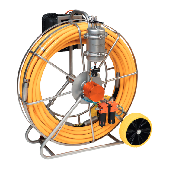
Start by placing the hose reel and the control unit where the
work will be performed. Then connect the power 110/220 V to
the control Unit.
Connect the compressed air from the compressor with the air
inlet (13.2) on the hose reel. In connection with the compres-
sor, use a refrigeration dryer in order to avoid freezing in the
small hoses and the sluice units.
Now guide the cutter out of the hose reel and into the pipe
where it will work. If the cutter needs to pass through a sharp
bend to reach the work site, the insertion should be followed
on the monitor (9.8) so the operator can lift/swivel the cutter
arm when it reaches the bend, thereby facilitating entry. Re-
member to lay
down the cutter arm again when the bend has been passed.
If a long distance must be travelled, it is recommended to use
the foot plate that is mounted on the frame when inserting and
removing the cutter.
The cutter is now in position and ready for operation.
Turn on the cutting air using the switch on the Control Unit
(9.9) and let it run for a while before opening the tap to the
camera's tank (7.5). Slowly lift the cutter arm by moving the
joystick (9.3) back towards the operator so that the cutting
head (8.7) touches the working area. For connector open-
ings, it is important that the cutter is moved backwards and
forwards. This is performed with the joystick (9.5) on the con-
nector while simultaneously rotating the cone milling tool. This
is performed by moving the joystick (9.13) to the right and left
respectively.
It is important to have worked a large part on the connector
before the cone milling tool goes through the sleeve, because
this minimises the risk of the cutter/cone milling tool getting
stuck inside the pipe. It is also recommended to reduce some
of the pressure on the cutter arm just before the cone milling
tool passes through the sleeve. This is performed by moving
the joystick (9.13) forward. In order to move farther forward or
backward than the hose length reaches, use the yellow hose to
push/pull the cutter into position.
The speed of rotation can be adjusted on a potentiometer on
the Control Unit. (9.12)
In order not to damage the conveying motor, it must be driven
back to the closed state before the cutter is withdrawn from
the tube after use. (8.1) The yellow hose is used to pull the
cutter back to the hose reel when the cutting is completed.
Remember to clean and lubricate the cutter according to
section (5.0) for service and maintenance of DC SUPER FLEX.
Close the tap to the camera's tank (7.5), disconnect the air and
power supplies.
Close the Control Unit and hang it back on the hose reel.
7
