3Shape TRIOS S3A-14 Manuel de configuration - Page 5
Parcourez en ligne ou téléchargez le pdf Manuel de configuration pour {nom_de_la_catégorie} 3Shape TRIOS S3A-14. 3Shape TRIOS S3A-14 14 pages.
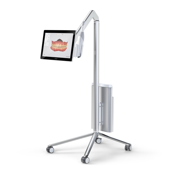
• Touch screen: Touch-enabled screen for real-time display of scanning
results generated by the TRIOS software, and for interacting with the
TRIOS software .
• The system standby button (S17) is on the back of the monitor .
• In the bottom (S18), there is a power socket (S19), a network (LAN)
connector (S20), and a fuse drawer (S21) . In the top of the backpack
(Figure 7), the dongles are inserted, see description below .
• USB wireless dongle (allows communication between scanner and
computer or cart)
• USB license dongle (access to 3Shape Software)
• USB wifi dongle (for connecting cart to wifi network)
• Bluetooth dongle (for connecting the cart to Bluetooth devicesas
keyboard and mouse)
• USB port (only MOVE+): The MOVE+ has a USB port (S29) .
The friction of the arm of the MOVE/MOVE+ cart that holds the scanner
and the display can be adjusted . The corresponding tool is provided with
the system . (Figure 8)
Step 1: Move the arm to the top-most position .
Step 2: Insert the tool into the hole on the bottom side of the arm,
located approx . half way along the arm .
Step 3: Turn the tool clockwise to increase friction, anticlockwise
to reduce friction .
Step 4: Adjust friction so that the monitor is steady (does not sink,
does not go up) in the following scenarions:
• Scanner is positioned in scanner holder
• Scanner is not positioned in scanner holder
IMPORTANT NOTICE
Maximum current available for the USB port is 200 mA .
System S3P furthermore comprises (Figure 3 and 4):
Pod, PS3-4 (S22) (Figure 3):
• A mount for the scanner
• A USB wireless dongle for the PC (S23)
• A USB license dongle
Pod with electronics, PS3-2 (Figure 4):
• A mount for the scanner with several connection sockets . On one side,
there is a single socket for the scanner . On the other side, there are two
connection sockets for the Ethernet cable to the PC and for the external
medical power supply, respectively .
• A USB license dongle
4.7 Setting up TRIOS
It is recommended that unpacking, assembly and connection of the TRIOS
IOS System be performed by TRIOS authorized technical service personnel .
It is recommended to fully charge batteries for the scanner before use .
CAUTION
If the system has just been delivered from a cold environ-
ment, let it adjust to room temperature to avoid internal
condensation and to allow for proper calibration .
CAUTION
Examine all parts of the system . Look for physical damage,
loose parts or signs of wear that could interfere with proper
use and functionality . Contact your service provider if there
is visible damage or malfunctioning .
System S3A (MOVE/MOVE+ cart) only
Please follow the steps below for assembling TRIOS IOS system (Figure 5):
Step 1: Place the MOVE/MOVE+ cart optimally in relation to the patient
chair and your work position . (S24)
Step 2: Attach the protection tip to the TRIOS scanner if not already
in place . (S25)
Step 3: Insert a battery fully into the rear of the scanner (S26) or insert
the TRIOS 4 cord into rear of scanner (S27) and connect the scanner
cable to the scanner connection socket on the MOVE/MOVE+ cart
behind the screen below the hinge (S28)
Step 4: Place the scanner in its designated scanner holder on the
MOVE/MOVE+ cart (Figure 2, S15) .
Step 5: Connect the MOVE/MOVE+ cart end of the power cable to the
socket in the bottom of the MOVE/MOVE+ cart's base . (Figure 2, S19)
Step 6: Connect the power cable to a grounded power outlet . Ensure
that the MOVE/MOVE+ cart is placed so it does not block the switch on
the mains socket outlet . To isolate the MOVE/MOVE+ cart and thus the
scanner from supply mains, unplug the flexible power cord from mains .
System S3P (Pod) only
Please follow the steps below for assembling TRIOS IOS system (Figure 6):
Before you start: Place the pod on a flat and horizontal surface optimally
in relation to the patient chair and your work position . Attach the protec-
tion tip to the TRIOS scanner if not already in place . For the wired scanner,
we recommend not to place the scanner onto the pod at this time yet, so
that it is easier to lift the pod while connecting cables in the following .
For the wired scanner (for the wireless scanner, begin with step 6)
Step 1: Connect the Ethernet cable to the pod . The cable goes into the left
connection socket on the back side of the pod (the side that has two
connection sockets) . If you need to release the Ethernet cable, press
on the small tab on the top of the connector .
Step 2: Connect the power supply to the pod . This cable goes into the con-
nection socket next to the Ethernet cable described in the previous step .
• To connect - push the plug into socket . There are red orien tation
dots on the socket and the plug that should match .
• To disconnect - pull on the outer release sleeve .
The indicator light will light green .
Step 3: Connect the TRIOS 4 cord to the scanner connection socket on
the front side of the pod (the side that has only one connection socket) .
• To connect - push the plug into the socket . There is a red orien tation
dot on the plug that should point upwards .
• To disconnect - pull on the outer release sleeve .
Now all connections to the pod are established, and you can place the
scanner onto the pod .
5