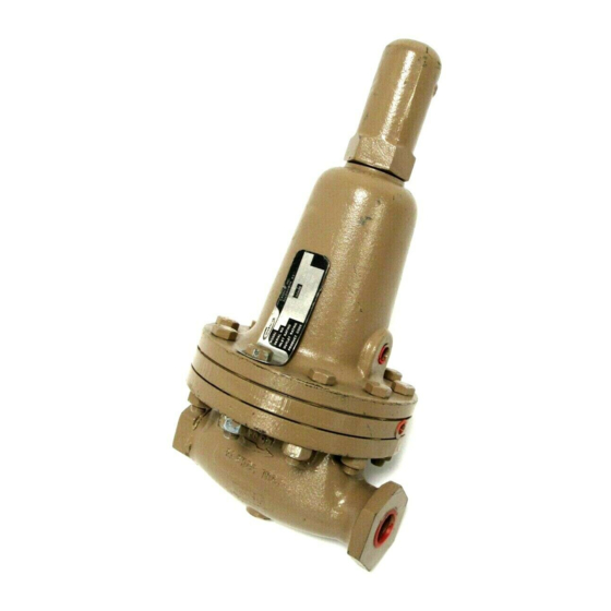
cashco 1000HP-1PLUS8 Manuel d'installation, d'utilisation et d'entretien - Page 8
Parcourez en ligne ou téléchargez le pdf Manuel d'installation, d'utilisation et d'entretien pour {nom_de_la_catégorie} cashco 1000HP-1PLUS8. cashco 1000HP-1PLUS8 17 pages. Differential pressure reducing regulator

c. Flow induced wear at expansion zone
where fluid turns to enter the piston (24)
center.
d. Where the piston (24) ribbed guides bear
(guide zone).
If wear is significant at any of these points,
both cylinder subassembly (21) and piston
sub as sem bly (24 or 24, 25, and 26) should
be replaced. (Cashco does not rec om mend
at tempt ing to replace the seat (21.2) by
press ing out and then repressing in. Cashco
also recommends that a cylinder (21) and
piston (24 or 24, 25 and 26) be replaced as
a set. Composition seat discs (25) may be
replaced individually.
6. If a composition (soft) seat trim design is
utilized, use the following sub-steps:
a. Tighten the "flats" of the seat disc screw
(26) within a vise. Firmly hand-grip the
piston (24) and turn CCW to loosen the
seat disc screw (26). If too tight, place a
screwdriver or similar rod within the pis ton
(24) port holes and rotate. Remove the
piston (24), and inspect for raised burrs
around the port holes if a device is used
to loosen; de-burr as required. NOTE: Do
not grip the piston (24) with a wrench.
b. Remove the seat disc (25) and clean the
recessed piston (24) area where the seat
disc (25) is placed. If the edges which form
the recess of the piston (24) are worn, also
replace piston (24) and seat disc screw
(26).
8
c. Place seat disc (25) into recessed end of
piston (24).
d. Place thread sealant on threaded portion
of seat disc screw (26), and manually
rotate piston (24) into seat disc screw (26)
(still fixed in vise) to secure seat disc (25).
Tighten seat disc screw (26) firmly. Do not
over-tighten to the point of embedding the
seat disc screw (26) into the seat disc
(25); the seat disc (25) should lay flat with
no rounded surface. A mechanical aid is
normally not re quired; hand tightening is
normally sufficient.
7. Insert piston assembly (24 - metal seat) (24,
25 and 26 composition (soft) seat) into end
of cylinder (21).
8. Place piston collar (23) over the end of piston
(24), ensuring that the spherical surface of
the piston (24) and the piston collar (23) bear
against each other.
9. Clean the body (1) cavity through the open ings.
Clean the "jet area" just inside the body (1)
outlet end through which the piston (24)
projects. Clean all parts to be reused.
10. Use special care cleaning the flat mating
surfaces of the body (1) and cylinder (21)
shoulder, as this pres sur ized joint is metal-to-
metal with no gasket. (See NOTE next step.)
11. Lubricate the cylinder (21) threads lightly with
thread sealant. Insert the entire trim stack into
the body (1) opening and screw until tightly
seated. Using the hammer and wrench han dle,
impact the cylinder (21) into the body (1).
NOTES: 1. Take special precaution to keep
pis ton collar from getting "cocked" at an angle
when inserted.
2. On 2" brass bodies (1) with brass trim, a TFE
body O-ring (43) is utilized to seal be tween the
body (1) and the cylinder (21) subassembly.
This O-ring is not indicated on drawings.
12. Inspect the body (1) outlet end to ensure that
the piston (24) is located nearly concentric to
the body (1) bore in the jet area with clear ance.
Under no con di tion should the piston (24)
be touching the body (1). Use two pencils or
similar shafts to place in inlet and outlet ends
of regulator and alternately push on each end
IOM-1000HP-Dif fer en tial
