FreeBytes RadioKit-120 Manuel d'assemblage et d'utilisation - Page 4
Parcourez en ligne ou téléchargez le pdf Manuel d'assemblage et d'utilisation pour {nom_de_la_catégorie} FreeBytes RadioKit-120. FreeBytes RadioKit-120 11 pages. 20μ cw ham radio transceiver kit
the transceiver may be connected to KEY(+) and KEY(-) pins while a small
speaker or earphone may be connected to SPK(+) and SPK(-) pins. S1-1 and
S1-2 pins are provided as a convenience if you want to bypass C12 variable
capacitor by the means of a switch during receive or transmit in order to
accomplish RIT or XIT functions.
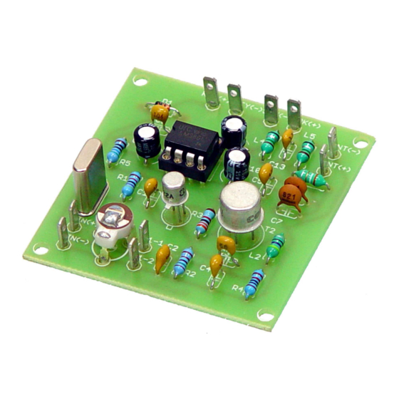
ASSEMBLING RadiØKit-120
Start construction by first identifying all the components included in the kit.
Make sure that nothing is missing and that all the indicated in the parts list
values are correct. In case of any trouble do not hesitate to contact us for help.
In order to help you identify the components all the color codes and markings
are mentioned in the parts list. First solder the resistors R1 to R5.
This is how the board should look after
soldering the resistors.
Then solder the inductors L1 to L5 followed by the capacitors C1 to C13.
The board after soldering the
inductors.