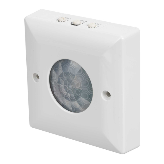
DANLERS CESF PIR Notes d'installation - Page 2
Parcourez en ligne ou téléchargez le pdf Notes d'installation pour {nom_de_la_catégorie} DANLERS CESF PIR. DANLERS CESF PIR 2 pages. Ceiling surface mounted pir occupancy switch
Également pour DANLERS CESF PIR : Manuel de démarrage rapide (2 pages), Manuel de l'utilisateur (2 pages)

Installation procedure
1. Please read these notes carefully before commencing work.
In case of doubt please consult a qualified electrician.
2. POSITIONING: The CESF PIR should be installed to achieve correct
coverage of the area, see diagram A. If the photocell override facility
is required, the switch must be located above an area where daylight
can give greater illumination than the artificial light. Avoid locating this
product where it is exposed to windy or drafty conditions (exposed
lobbies, open ceiling voids or near ventilation fans) or near heat
sources. To cover large areas CESF PIRs should be spaced in a 5
metre grid formation.
3. The greatest energy savings will be made if each CESF PIR controls
an independent set of lamps. They can be wired in parallel but this
should ideally be limited to three, see diagram D.
4. Make sure the power is isolated from the circuit.
The CESF PIR should be connected as shown in diagrams C & D:
L - Live in.
N - Neutral in.
Start-up mode
When the CESF PIR is powered up, it will switch on the load for 1
minute, the load will then switch off and the CESF PIR will enter its
Operating Mode. If a manual override-off switch is positioned before
the CESF PIR in the circuit (diagrams C & D, note 1) it will do this
each time the wall switch is switched on. Alternatively, if the wall switch
is placed after the PIR (diagrams C & D, note 2) it will not enter the
start-up mode each time.
Time and Lux set-up
For convenience, ensure that the TIME is set to the minimum when
setting up the LUX level. Afterwards set the TIME to a value suitable
for the application, making reference to diagram B.
The LUX is best set up when the local ambient light is at approximately
the minimum desired working light level, a lux meter placed on the
surface under the CESF PIR may help. With the LUX set fully clockwise
wait for the CESF PIR to switch off. Rotate the LUX adjuster slowly
anticlockwise (- to +), whilst waving your hand approximately 1m below
the PIR, until the load switches on.
SL - Switched Line out.
A: Detection diagram
For optimum coverage
recommended mounting
height: 2.4 to 5m
up to 5m
up to 7m
B: Adjusting time, lux
and sensitivity
C: Wiring diagram,
single PIR
L
N
D: Wiring diagram, multiple PIRs
Note 1: Optional manual wall switch
for overriding off
L
L
L
N
N
SL
SL
230 VAC
N
Strong detection zone
i.e. person moving arm
or walking towards PIR
Secondary detection zone
i.e. person walking
perpendicular to PIR
Typical settings
2m30s
1m15s
5m
40s
10m
20m
20s
1000
10s
40m
∞
100
66%
min
max
max
min
TIME
LUX
Note 1: Optional
Note 2: Alternative
position for optional
manual wall switch
wall switch
for overriding off.
L
SL
N
230 VAC
Note 2: Alternative
position for optional
wall switch.
L
N
SL
100%
min
max
SENS
load
load
