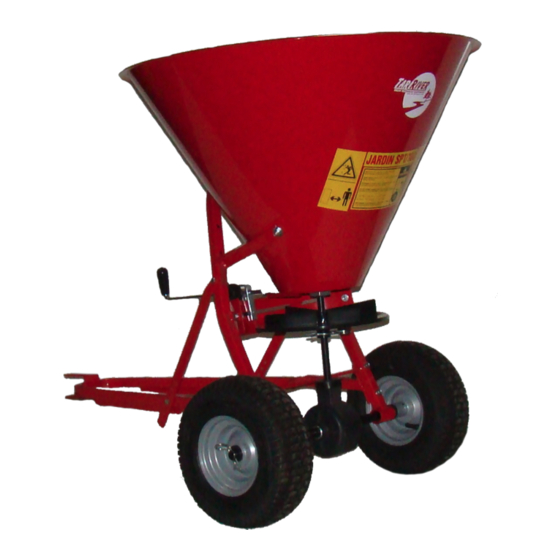
Belco TAR RIVER PTS-100 Manuel de l'opérateur - Page 7
Parcourez en ligne ou téléchargez le pdf Manuel de l'opérateur pour {nom_de_la_catégorie} Belco TAR RIVER PTS-100. Belco TAR RIVER PTS-100 16 pages. Ground driven spreader

1. Begin assembly by sliding the threaded bushing (#7) through the bottom center hole of the hopper. Fas-
ten the mobile shutter (#48) to it with the nut (#47). Make sure the slots in the mobile shutter are facing
away from the bottom of the hopper. Tighten the nut securely.
2. Bolt the guard (#14) to the frame (#11) with the 8 x 16mm (#16) bolts, washers and hex nuts.
3. Slide the Spinner disc (#46) and the hopper with mobile shutter attached, over the gearbox shaft. Secure
the spinner disc in place with the R pin (#43) and secure the rear of the hopper to the square tubing sec-
tion of the frame (#11) using the 8 x 40 carriage bolts (#8), 8mm washer (#9) and hex nut.
4. Place the dust cap and agitator (#4) over the output shaft and secure it using the 6 x 30mm (#5) bolt and
lock nut.
5. Place the distributor shield (#3) inside the hopper (#2) and fasten with the two M8x20 carriage bolts (#50),
M8 washers (#9) and M8 hex nuts (#10) that connect the sides of the frame to the hopper.
6. Slide the flow control assembly (#19) into the slot of the mobile shutter (#48) and fasten to the guard (#14)
with the adjustment knob (#20) and M8 washer (#14).
7. The wheel hubs are offset and are mounted on the shaft (#28) with the long end (that with the hole) to the
inside. Assemble the wheels, followed by the 20mm washer (#31). Secure in place with
the bent R cotter pin (#45).
through the hole in the hub and axle. Secure in place with the washer and lock nut.
8. Attach the drawbar tongue (#51) to the square tubing of the frame utilizing the right plate (#17)
and left plate (#18) and the 8 x 40mm bolts (#15), washers and nuts. Select the hole in plate (#17)
that allows the spreader to run parallel to the ground. The correct hole will depend on the hitch
height of the towing unit.
9. Attach plates (#21 & #22) by sliding the round stock ends of these two plates though the tubes that are
welded to the ends of the tongue. Bolt the outer end to the frame (the two plated should be angled up-
wards with the stock ends pointed inwards after they are bolted).
10. Tighten all hardware.
Assembly Instructions
On the right wheel (#25), insert the M6x45 bolt (#26)
