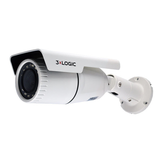
3xLogic VX-2A-B-IWD (R) Manuel de démarrage rapide - Page 4
Parcourez en ligne ou téléchargez le pdf Manuel de démarrage rapide pour {nom_de_la_catégorie} 3xLogic VX-2A-B-IWD (R). 3xLogic VX-2A-B-IWD (R) 13 pages.

1.1
Installation
There is only one type of mounting explained in this manual. Refer to the device's installation guide for more
various mounting types.
Steps:
1).
Place the installation template (paper)
included in the package on the desired
installation surface.
2).
Drill three holes in correct positions based on
the template paper, and insert the anchor
blocks into the holes.
3).
Attach the silicon waterproof band included in
the package to the camera's mounting surface
by aligning it with the three alignment holes.
4).
Connect the required cables including a power
cable and a LAN cable (or PoE cable) to the
device. Refer to Section 1:
Positions
for more details.
5).
Place the camera body to match the three
alignment holes with the three anchor blocks,
and hold the camera against the surface where
the camera will be mounted.
6).
Tighten the anchor blocks with the screws
(M4x30).
7).
Adjust the heading direction of the camera
with the provided hex wrench (3mm). Please
refer to Section 2:
Camera
for more details.
8).
Adjust zoom and focus of the camera. Refer to
Section 3:
Adjusting Zoom and Focus
details.
9).
Attach the lens cover on the main body by
rotating it clockwise.
CAUTION:
Sealing gaps is recommended as gaps may appear after the camera installation. Gaps may cause problems such
as moisture, water leakage and etc., which negatively affects the operation of the camera if gaps remain
unsealed.
CAUTION:
To prevent products from damage, place the camera on stable and non-vibrating surfaces If the stability is in
doubt, consult safety personnel for reinforcements, and then proceed with the installation.
10225 Westmoor Drive, Suite 300, Westminster, CO 80021 | www.3xlogic.com | (877) 3XLOGIC
Part Names and
Adjusting Angle of the
for more
VISIX Camera Quick Start Guide | VX-2A-B-IWD (R)
4
