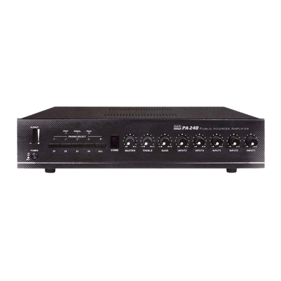
DAPAudio PA240 Manuel du propriétaire - Page 7
Parcourez en ligne ou téléchargez le pdf Manuel du propriétaire pour {nom_de_la_catégorie} DAPAudio PA240. DAPAudio PA240 18 pages. Public address amplifier

12-15) INPUT 1-4: These four unbalanced combination jack 6.3mm inputs, dynamic microphone
(30-600 )or a high level sound source (e.g. AM/FM tuner, cassette desk, CD player, etc.).
INPUT 1 has a "Voice Priority" function that mutes all the other inputs as soon as a message is
transmitted with a microphone; it is possible to exclude this function by calling a qualified SERVICE
CENTER.
16) "AUX IN" inputs
The "R" and "L" sockets permit the input of the right (R) and left (L) channels of an audio source with a
high-level output signal, such as an AM/FM tuner, a cassette deck, a CD player, etc. Use input
sensitivity switch (17).
17) "PREAMP OUT" socket
This output sends the sum signal of all the connected sources and can be used to feed an external
power amplifier, a signal processor (e.g. an equalizer), or any other external device. The unbalanced
signal is affected by the individual input controls. Before using the PREAMP OUT you have to remove
the bridging-strip between this socket and the "MAIN IN" socket (18) and preamp out terminal
sockets.
18) "MAIN IN" socket
After removing the bridging-strip between the "PRE OUT" and the "MAIN IN" terminals you can include
an external signal processor (e.g. an equalizer) in the audio-chain between the pre-amplifier and the
power output stage of the power amplifier. This opportunity provides a proper solution whenever shaping
or improving the audio signal is necessary (adjusting delay times, equalizing, eliminating unwanted
feedback from the mic to the loudspeakers, etc.). The input is unbalanced.
19) Input Sensitivity Switch Line / Mic / Phantom Power 24V for INPUT 1, INPUT 2, INPUT 3 and INPUT 4
By setting this switch to the LINE position the IN1, IN2, IN3, IN4 input can be connected to an audio
source with high level signal output. By setting the switch to the MIC position the IN1, IN2, IN3, IN4 input
can be connected to a dynamic microphone with low impedance. By setting the switch to the 24V
position connects the "24V" phantom supply on XLR of pin2 and pin3 of inputs IN1, IN2, IN3, IN4
necessary to operate condenser type microphones, which require this type of external supply.
It is recommended to use this switch with the general volume set on minimum.
20) Input sensitivity switch (AUX IN)
Setting this switch to the "CD" position, the "AUX IN" input is suitable for connecting to a CD player
signal output. By setting this switch to the "TUNER" position, the "AUX IN" input is suitable for
connecting to an AM/FM radio. By setting the switch to the "TAPE" position, the "AUX IN" input is
suitable for connecting to a cassette player.
21) Music signal monitor output level control
The control lets you individually set the volume of the sound source output that is connected to the
"MONITOR OUTPUT 1W/8 " (25) terminals. Turning the controls clockwise, increases the volume of
5
Fig. 2
