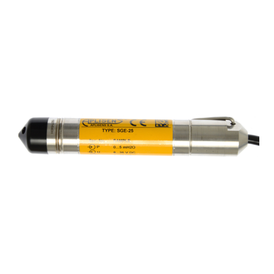
Aplisens SGE-25S Manuel de l'utilisateur - Page 11
Parcourez en ligne ou téléchargez le pdf Manuel de l'utilisateur pour {nom_de_la_catégorie} Aplisens SGE-25S. Aplisens SGE-25S 16 pages. Hydrostatic level probes
Également pour Aplisens SGE-25S : Manuel de l'utilisateur (20 pages)

7.1.1.
Depth probe with the internal PT temperature sensor.
Electrical connections and colours of the wires in the depth probe cable with an output signal
of 4...20 mA with resistance temperature sensors:
Depth probe:
− red: „+"
− black: „-"
− green: cable shield (if led out)
Resistance sensor (RTD):
− white
− white
− brown
− brown
− white
− brown
− brown
7.2. Power supply
7.2.1. Power supply voltage
Supply cables may be live.
There is a risk of electric shock and/or explosion.
Installation in potentially explosive atmospheres must comply with local standards
and regulations.
Table 2. Permissible power supply voltage.
Probe type
SGE-25, SGE-25/Hastelloy,
SGE-25S, SGE-25C
SGE-25, SGE-25S, SGE-25C
– Ex version
SGE-25, SGE-25S, SGE-25C
SGE-25, SGE-25S, SGE-25C
- TR version*
SGE-16
SGE-16
* TR version- made for measurements in fast-moving processes.
** TR Exi version
7.2.2. Resistance load in supply line
Power line resistance, power source resistance and additional series resistances increase
the voltage drops between the power source and the probe transducer. The maximum current under
normal operating conditions is 0.02 A. The maximum value of resistance in the supply circuit
(together with the supply line resistances) is given by the curves:
Revision 01.A.001/2021.09
Sensor in four-wire
connection
Sensor in three-wire
connection
Output signal
4...20 mA
4...20 mA
0...10 V
4...20 mA
4...20 mA
0...5 V
0...3,3 V
MIN. Supply
voltage
8 V DC
9 V DC
13 V DC
10,5 V DC
8 V DC
5 V DC
3,3 V DC
EN.IO.SGE
MAX Supply
voltage
39 V DC
28 V DC
30 V DC
36 V DC
28 V DC**
36 V DC
36 V DC
36 V DC
11
