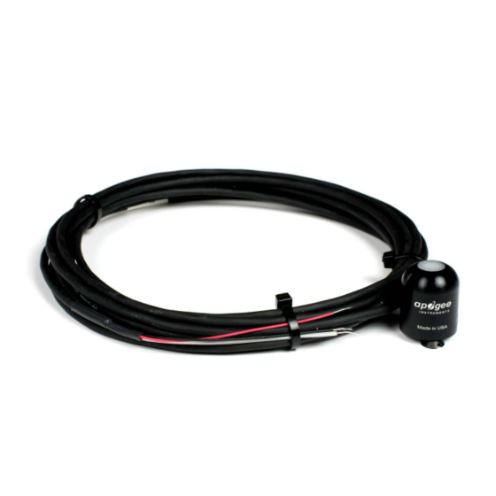
Apogee SP-214 Manuel du propriétaire - Page 18
Parcourez en ligne ou téléchargez le pdf Manuel du propriétaire pour {nom_de_la_catégorie} Apogee SP-214. Apogee SP-214 18 pages. Pyranometer
Également pour Apogee SP-214 : Manuel du propriétaire (19 pages)

18
TROUBLESHOOTING AND CUSTOMER SUPPORT
Independent Verification of Functionality
Apogee models SP-110 and SP-230 pyranometers are self-powered devices and output a voltage signal proportional to
incident shortwave radiation. A quick and easy check of sensor functionality can be determined using a voltmeter with
millivolt (mV) resolution. Connect the positive lead wire from the voltmeter to the white wire from the sensor and the
negative (or common) lead wire from the voltmeter to the black wire from the sensor. Direct the sensor diffuser toward a
light source and verify the sensor provides a signal. Increase and decrease the distance from the sensor head to the light
source to verify that the signal changes proportionally (decreasing signal with increasing distance and increasing signal with
decreasing distance). Blocking all radiation from the sensor should force the sensor signal to zero.
The heaters inside Apogee model SP-230 are designed to mitigate effects from snow, frost, and dew by warming the sensor
body temperature approximately 3 C above ambient air temperature, while under conditions of no solar loading or radiant
heating. A quick and easy check of heater functionality can be accomplished with an ohmmeter. Connect the lead wires of
the ohmmeter to the yellow and blue wires from the sensor. The resistance should read approximately 780 Ω ± 1%.
Compatible Measurement Devices (Dataloggers/Controllers/Meters)
Models SP-110 and SP-230 pyranometers are calibrated with a standard calibration factor of 5.0 W m
-2
per mV, yielding a
sensitivity of 0.2 mV per W m
. Thus, a compatible measurement device (e.g., datalogger or controller) should have
-2
resolution of at least 0.2 mV, in order to provide shortwave radiation resolution of 1 W m
-2
.
An example datalogger program for Campbell Scientific dataloggers can be found on the Apogee webpage
at http://www.apogeeinstruments.com/content/Pyranometer-Unamplified.CR1.
Effect of Cable Length
When the sensor is connected to a measurement device with high input impedance, sensor output signals are not changed
by shortening the cable or splicing on additional cable in the field. Tests have shown that if the input impedance of the
measurements device is 1 mega-ohm or higher then there is negligible effect on the pyranometer calibration, even after
adding up to 100 m of cable. Apogee model SP series pyranometers use shielded, twisted pair cable, which minimizes
electromagnetic interference. This is particularly important for long lead lengths in electromagnetically noisy environments.
Modifying Cable Length
See Apogee webpage for details on how to extend sensor cable length
(http://www.apogeeinstruments.com/how-to-make-
a-weatherproof-cable-splice/).
APOGEE INSTRUMENTS, INC. | 721 WEST 1800 NORTH, LOGAN, UTAH 84321, USA
TEL: (435) 792-4700 | FAX: (435) 787-8268 | WEB: APOGEEINSTRUMENTS.COM
Copyright © 2018 Apogee Instruments, Inc.
