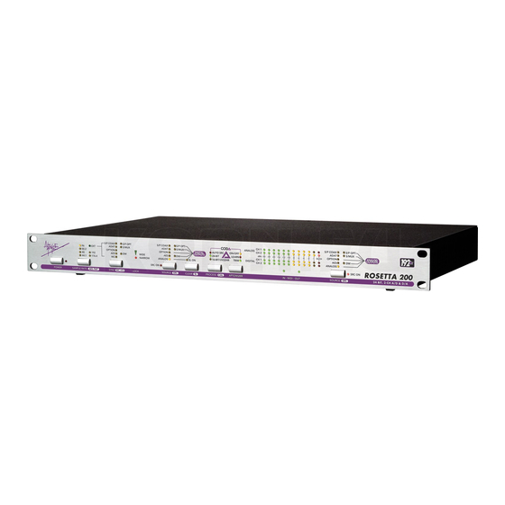
Apogee Rosetta 200 Manuel de l'utilisateur - Page 14
Parcourez en ligne ou téléchargez le pdf Manuel de l'utilisateur pour {nom_de_la_catégorie} Apogee Rosetta 200. Apogee Rosetta 200 20 pages. 2-channel 24 bit, 192 khz, ad/da converter
Également pour Apogee Rosetta 200 : Fiche technique (2 pages), Livre blanc (2 pages)

ROSETTA 200 – User's Guide
Navigating the Front Panel -
Sample Rate Conversion - As the number of digital audio sample rates increases, the necessity for high quality conversion
between these rates grows. For the first time on an Apogee product, sample rate conversion is offered on the Rosetta 200. To
employ sample rate conversion:
1 Connect the source to one of the Rosetta 200's digital inputs and set SOURCE (to Digital Outputs) to the
appropriate setting.
2 Connect the destination to a Rosetta 200 digital output.
3 Select the desired output sample rate
4 Press and hold the SOURCE (to Digital Outputs) button until the SRC LED lights.
5 Keep in mind that SRC may be applied to one digital input only.
To get a better sense of SRC's function, here are a few examples where it might be employed:
96k/24 bit to CD (44.1kHz 16 bit) – Perhaps the most common application of SRC is the conversion of high sample rate
audio to the Compact Disc rate of 44.1kHz. By using SRC in conjunction with Apogee's UV22 bit resolution reduction
algorithm, CD transfers retain the quality and resolution of the original high sample rate/ bit depth audio. Follow these
steps to convert a 96k, 24 bit AES digital input to a 44.1kHz, 16 bit digital output.
1 Connect the 96kHz signal to AES Input 1, connect the appropriate digital output to the destination machine.
2 Set SAMPLE RATE to 44.1
3 Set SOURCE (to Digital Outputs) to AES; set SOURCE (to Analog Outputs) to AES to monitor the converted
signa via the analog outputs.
4 Press and Hold SOURCE (to Digital Outputs) and verify that the SRC LED next to each SOURCE button is lit
5 Press PROCESS to select 16 bit/UV22HR
6 The signal routed to all digital outputs is now 44.1kHz 16-bit.
Monitoring or transferring from non-synchronous digital sources quickly – To monitor or transfer from non-
synchronous digital sources such as DAT machines, CD players and synth modules with digital outputs, usually it's
necessary to lock the entire digital system to that source, potentially degrading clock quality and often disrupting work flow.
When AUTO SRC is engaged, it's possible to set either SOURCE path to a non-synchronous input without modifying the
Rosetta 200's sample rate or clock source. For example, if the Rosetta 200 is the clock master of a digital system running at
96kHz, it's possible to input signals from a 48kHz synth without clocking to that input or changing sample rate.
14) CALIBRATION – Press and hold the PROCESS button to engage CAL mode. The following buttons are
used to change parameters in CAL mode:
Once in CAL mode, press PROCESS to set the channel(s) to calibrate, as indicated by the blinking
"Ouch" LED. It's possible to calibrate each channel individually or both A/D or D/A channels
simultaneously.
Press + (CLEAR) to raise the calibration level of the selected channel(s), press – (SOURCE to Digital
Outputs) to lower the calibration level.
In calibration mode, the LED meters display a "zoomed-in" range of digital levels between –20 and –10
dBFs, as shown in Figure 7 (pg 10); each column of LEDs now corresponds to a 1 dB change in level.
To aid in precise calibration, a single LED lights ONLY when the corresponding channel's actual level
is within +/- .1dB of the specified level, otherwise adjacent LEDs light to show that the actual level is
between two specified levels. For example, if a tone connected to the analog inputs results in a digital
level of -16.4 dBFs, both the "-16" and "-17" LEDs will light. When the actual level is within plus or minus
.1 dB of for example, -12 dBFs, ONLY the "-12" LED will light. Please note that when the Rosetta 200 is
reset, it is calibrated to the default level of +4 dBu = -16 dBFs (+/- 0.2 dB).
continued
14
6
APOGEE ELECTRONICS
